Cutting tool

a cutting tool and cutting edge technology, applied in the field of cutting tools, can solve the problems of inconvenient and time-consuming process, inconvenient positioning and attaching the guiding pads to the steel body, and the inability to braze the cutting tips to the steel body

Active Publication Date: 2009-04-30
ISCAR LTD
View PDF21 Cites 27 Cited by
  • Summary
  • Abstract
  • Description
  • Claims
  • Application Information

AI Technical Summary

Problems solved by technology

Such an arrangement encounters a disadvantage of the necessity to braze the cutting tips to the steel body.
Moreover, the need to accurately locate and attach the guiding pads to the steel body involves an expensive and time consumin...

Method used


Image

  • Cutting tool
  • Cutting tool
  • Cutting tool

Examples


Embodiment Construction

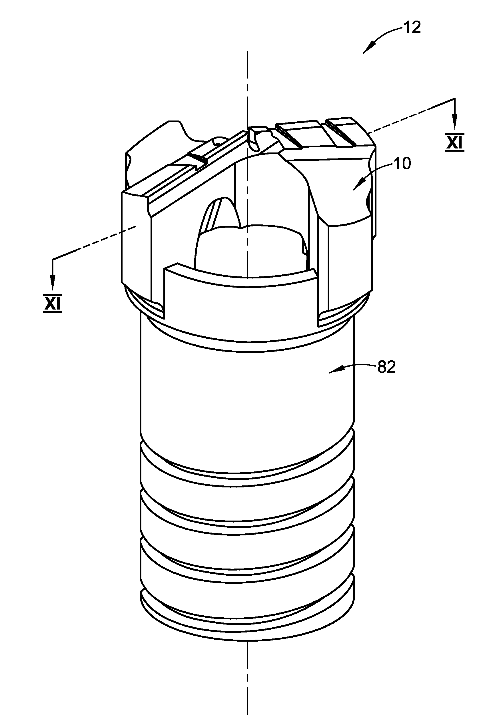
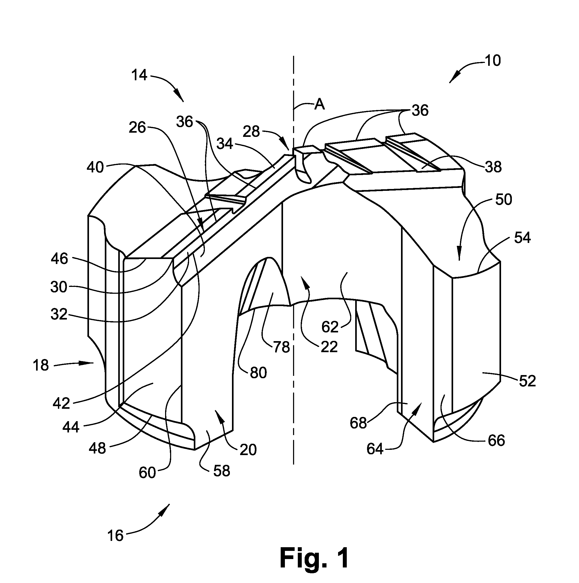
[0055]Attention is first drawn to FIGS. 1 to 5 that show a cutting head 10 of a drilling cutting tool 12 (shown in FIGS. 7, 9 and 11) in accordance with the present invention. The cutting head 10 may be manufactured by form-pressing and sintering carbide powders or by injection molding techniques. The cutting head 10 has a longitudinal axis A and comprises a cutting head forward end 14, a cutting head rear end 16 distal the cutting head forward end 14 and a peripheral surface 18 therebetween. It is understood that terms used throughout the specification, such as “forward”, “rearward” and the like, are used for description purposes only and are not intended to limit the scope of the invention as hereinafter claimed.

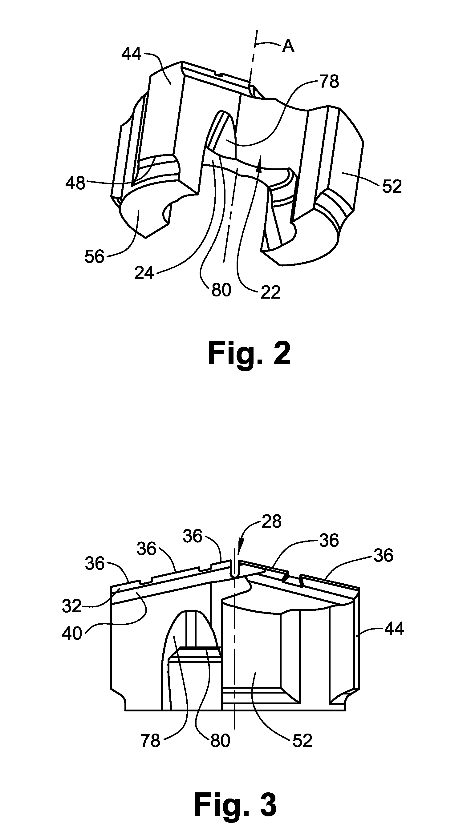
[0056]Two diametrically opposite major guiding segments 20 extend from the longitudinal axis A and from the cutting head forward end 14 to the cutting head rear end 16. The major guiding segments 20 join at a cutting head central portion 22 that has a central portion base ...


PUM

PropertyMeasurementUnit
Angleaaaaaaaaaa
Angleaaaaaaaaaa

Abstract

A cutting tool of the sort used for deep hole drilling has a cutting head mounted on a shank. The cutting head is formed asymmetrically with respect to a longitudinal axis and has at least one cutting edge. The cutting head has guiding segments that extend from a forward end to a rear end of the cutting head. Each of the guiding segments has a guiding pad in the periphery thereof. A forward end of the guiding pad lies on a cylindrical envelope defined by the cutting diameter of the cutting tool. A rear engagement portion of the cutting head is engaged with a forward engagement portion of the shank. The cutting head is made from sintered carbide powders and the guiding pads are integrally formed with the cutting head.

Description

FIELD OF THE INVENTION[0001]The present invention relates to cutting tools for deep hole drilling.BACKGROUND OF THE INVENTION[0002]Such cutting tools usually comprise an elongated steel body having a through bore that extends from the body rear end and opens into the body forward end. A hard metal cutting tip is typically brazed in the forward end of the steel body. In order to guide and stabilize the cutting tool through the cutting operation, guiding pads are attached to the periphery of the steel body. Such an arrangement encounters a disadvantage of the necessity to braze the cutting tips to the steel body. Moreover, the need to accurately locate and attach the guiding pads to the steel body involves an expensive and time consuming process.[0003]US Patent Application Publication No. US 2005 / 0025594 A1 discloses an edge-carrying drill body having a front head and a rearwardly extending hollow shaft adapted for connection with a tube, the front head being configured symmetrically ...

Claims


Application Information

Patent Timeline
IPC IPC(8): B23B51/00
CPCB23B51/04Y10T408/8973B23B2240/08B23B2251/02B23B2251/14B23B2251/422B23B2251/46B23B2251/56Y10T408/9098Y10T408/78Y10T408/9097Y10T408/909Y10T408/5586Y10T408/906Y10T408/907B23B2200/204B23B51/063
Inventor DRORI, GIDEONKISOS, YAAQOVGONEN, EITANMEN, DANIEL
Owner ISCAR LTD
Why Eureka
Try Eureka