Valve element, valve, selector valve, and trap device

a trap device and valve element technology, applied in the direction of water supply installation, fluid pressure control, instruments, etc., can solve the problems of increasing the volume of the entire device, difficulty in checking whether the sealing portion is present, and the valve switching portion and the entire device become bulky. , to achieve the effect of small installation space, simple structure and wide application rang

Inactive Publication Date: 2009-05-07
TOKYO ELECTRON LTD
View PDF1 Cites 16 Cited by
  • Summary
  • Abstract
  • Description
  • Claims
  • Application Information

AI Technical Summary

Benefits of technology

[0036]A valve comprising the valve element according to the present invention has a wide application range despite the simple structure and a small installation space, and can be used as an opening / closing valve represented by, e.g., an L-type valve, a switching valve, or the like. The simple structure facilitates trouble identification and maintenance.
[0037]If the valve element has a double seal structure, a leak checking gas is introduced to the gap between the seal portions in the sealing state, and gas leak is monitored by flow rate measurement or the like, the valve can be utilized in a variety of applications as a highly reliable valve mechanism with which the sealing properties of the valve element can be grasped easily.

Problems solved by technology

Where the plurality of valves are provided, however, the space necessary to set the valves of the switching portions and pipes increases, and the entire device becomes bulky.
Although the switching mechanism of patent document 1 is excellent in the sealing properties and sealing response in this manner, it has difficulty in checking whether the seal portion is reliably sealed. troubled portion is difficult to identify, and maintenance takes time, leaving room for improvement.

Method used


Image

  • Valve element, valve, selector valve, and trap device
  • Valve element, valve, selector valve, and trap device
  • Valve element, valve, selector valve, and trap device

Examples


Embodiment Construction

[0056]Preferred embodiments of the present invention will be described with reference to the accompanying drawings.

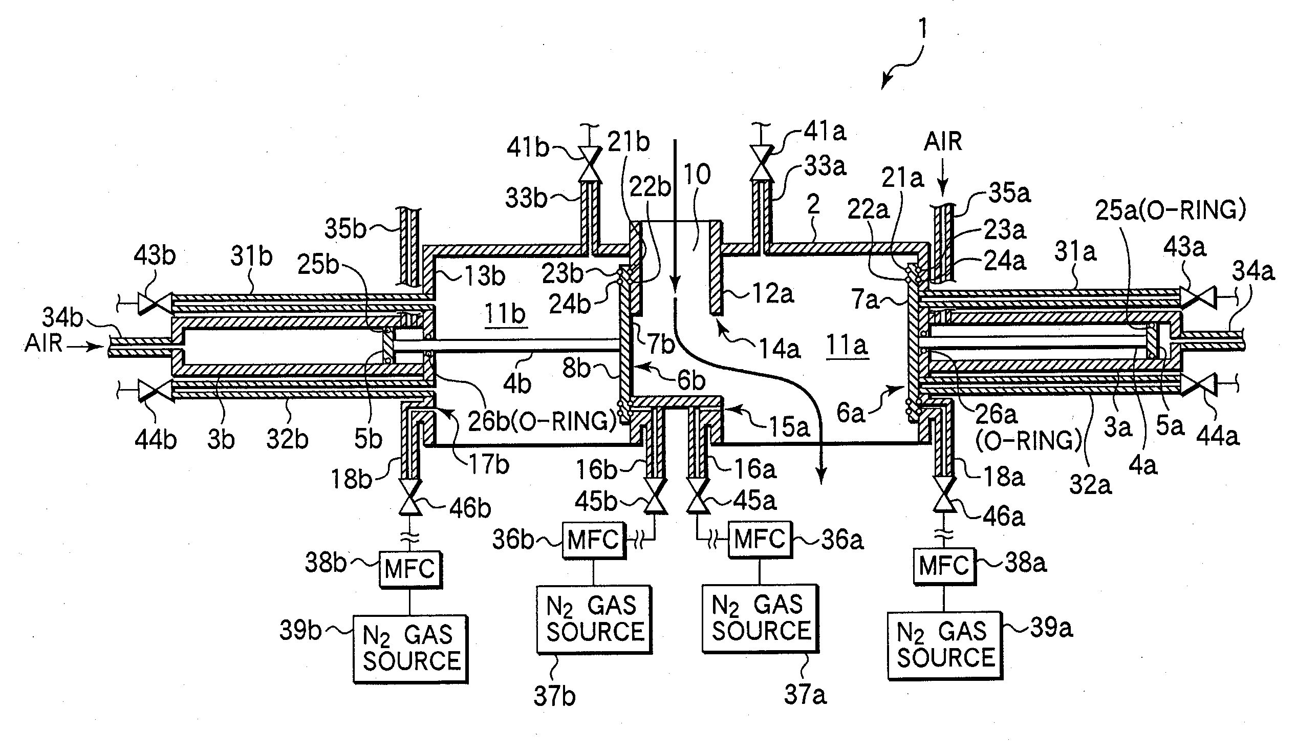
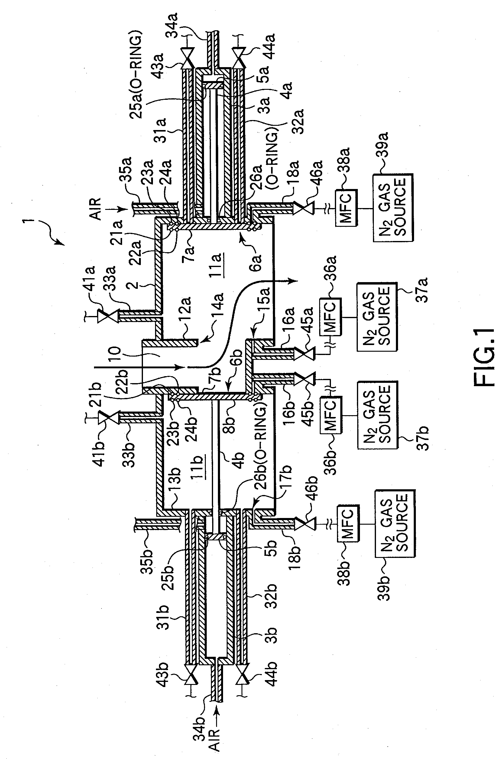
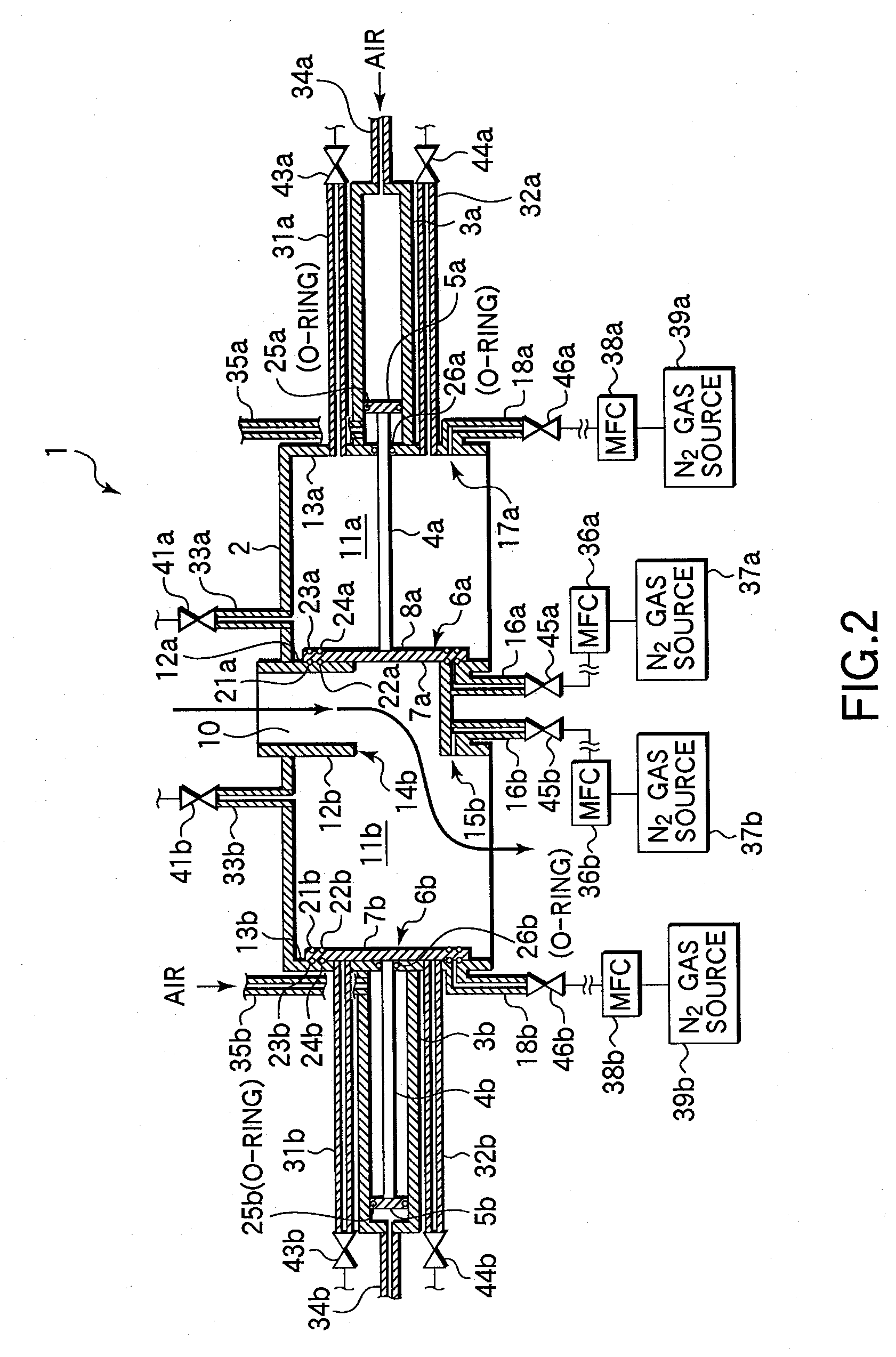
[0057]FIGS. 1 and 2 are sectional views showing the schematic arrangement of a valve mechanism according to an embodiment of the present invention. A valve 1 can be suitably used as a switching means or the like for alternately switching the flow channels of an exhaust gas flowing into a trap device for trapping substances in the exhaust gas from, e.g., a vacuum process chamber. The valve 1 is provided with an in-flow portion 10 through which a fluid flows into a housing 2. The valve 1 is almost axis-symmetric about the in-flow portion 10 as the center. More specifically, a first flow channel 11a and a second flow channel 11b are formed in the housing 2 with the in-flow portion 10 in between. A sealing plate 6a serving as a valve element driven by an air cylinder 3a is provided in the first flow channel 11a. A sealing plate 6b serving as a valve element driven by an air...


PUM


Abstract

When supplying a fluid to a first flow channel (11a) of a valve (1), air is introduced into an air cylinder (3a) from an air introduction channel (35a). An operating plate (5a) thus slides and drives a shaft (4a) to move backward to such a position that a second sealing surface (8a) of a sealing plate (6a) abuts against a wall (13a). An air cylinder (3b) is moved forward to such a position that a sealing surface (7b) of a sealing plate (6b) abuts against a wall (12b), thereby sealing an opening (14b).

Description

TECHNICAL FIELD[0001]The present invention relates to a valve element, a valve, a switching valve, and a trap device and, more particularly, to a valve element, a valve, a switching valve, and a trap device comprising the switching valve, which are suitably used in a discharge channel through which an exhaust gas is discharged from, e.g., a vacuum apparatus.BACKGROUND ART[0002]In manufacturing a device such as an electronic component, a substrate such as a semiconductor wafer or a glass substrate undergoes various types of processes such as film formation or etching in a process chamber such as a vacuum chamber. In this process, the process chamber is connected to an exhaust channel, and exhaust is performed through the exhaust channel. An unreacted process gas, a reaction product, and the like mixing in the exhaust gas include a toxic substance and a recyclable substance. Accordingly, a trap device is provided for trapping the toxic substance and recyclable substance so they will n...

Claims


Application Information

Patent Timeline
Patent Type & Authority Applications(United States)
IPC IPC(8): F16K5/00E03B1/00
CPCF16K11/044F16K11/207H01L21/67017F16K51/02F16K49/002Y10T137/87917
Inventor TSUDA, EINOSUKE
Owner TOKYO ELECTRON LTD
Why Eureka
Try Eureka