Embossing Roller And Method For The Manufacturing Thereof

a technology of embossing rollers and manufacturing methods, which is applied in the field of embossing rollers, can solve the problems of increasing the cost of the individual embossing roller production, and long processing operations that involve these techniques. the effect of cost reduction

Active Publication Date: 2009-05-07
FABIO PERINI SPA
View PDF44 Cites 18 Cited by
  • Summary
  • Abstract
  • Description
  • Claims
  • Application Information

AI Technical Summary

Benefits of technology

[0019]An object of the present invention is to provide a manufacturing process or method for producing embossing rollers that will enable maintenance of the advantages of incision obtained using a hob, i.e. a chip-removal machining, as compared to chemical, laser or other methods of incision, with a further reduction in the costs and production times.

Problems solved by technology

The processing operations that involve these techniques are particularly long and costly.
The grinding process following the hob machining of the embossing roller lengthens considerably the machining time and involves an increase of the cost for the production of the individual embossing roller.
Since the consistency and strength of the weblike material are relatively low, the pressures that can be exerted to deform it are also relatively low in order not to tear or break down too much the fibres of the weblike material itself, with consequent loss of mechanical characteristics of strength.
The embossing rollers obtained by machining using a hob and subsequent grinding always present protuberances all of the same height in so far as, in the current state of the art, it would be very difficult or even impossible to perform a selective grinding of the protuberances themselves.

Method used


Image

  • Embossing Roller And Method For The Manufacturing Thereof
  • Embossing Roller And Method For The Manufacturing Thereof
  • Embossing Roller And Method For The Manufacturing Thereof

Examples


Embodiment Construction

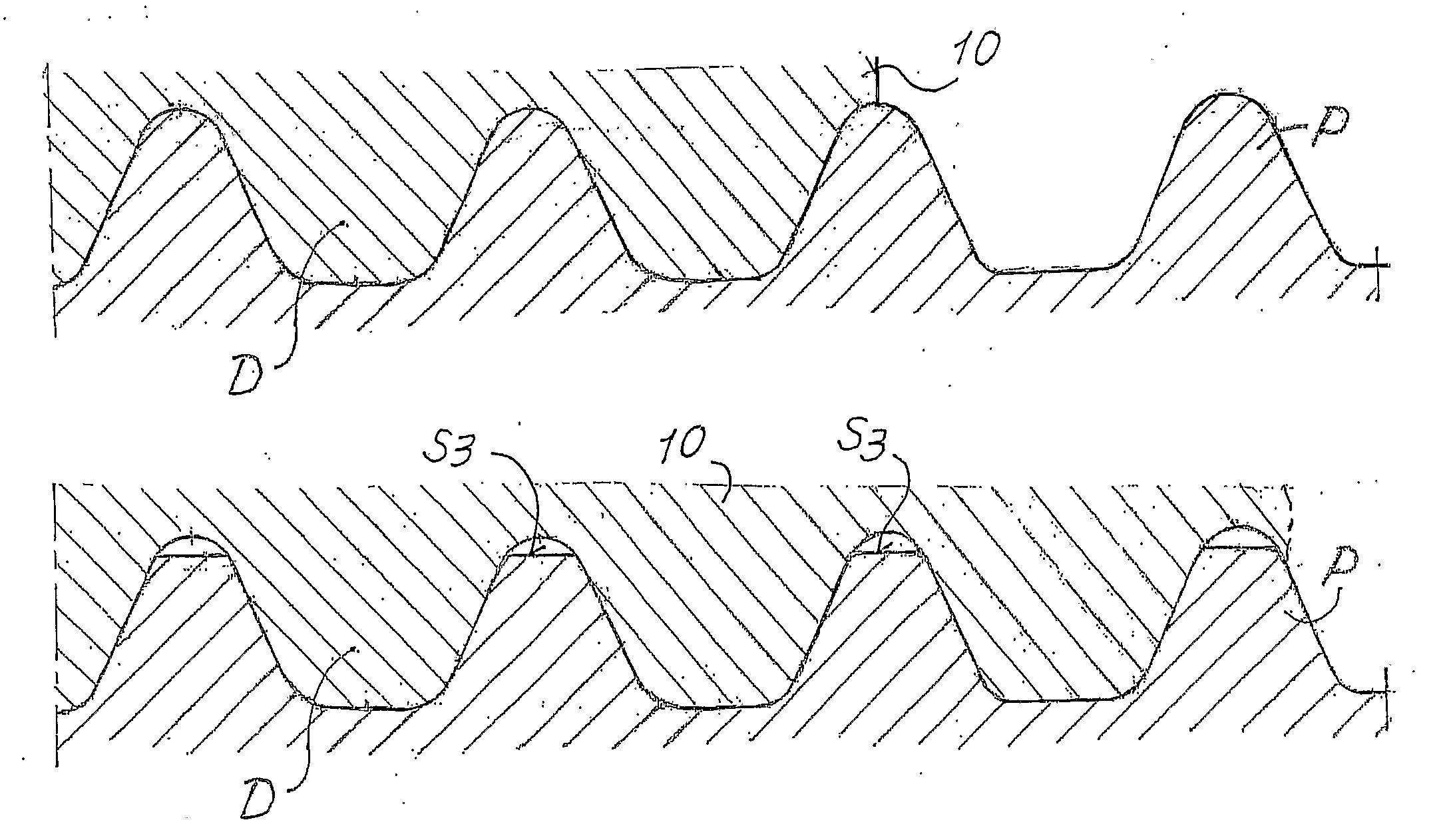
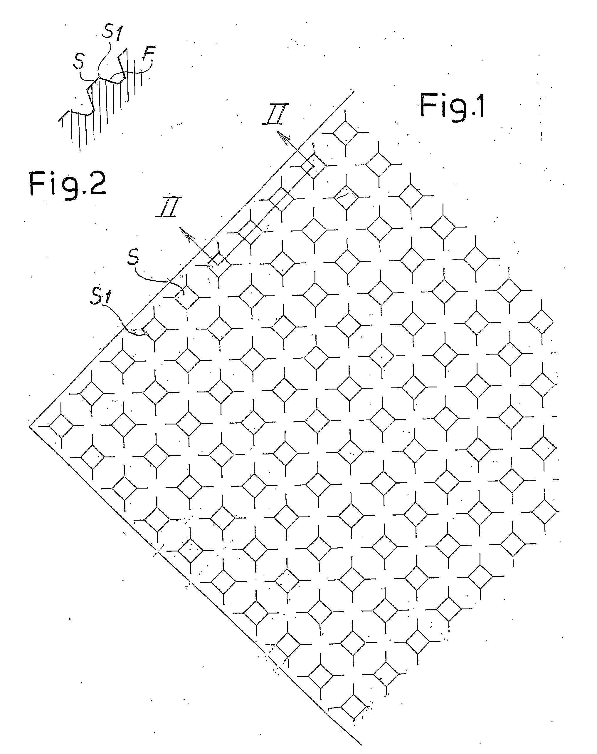
[0053]FIGS. 1 and 2 show the plane development and cross-sectional view of a roller machined with a double pass of a hob and subsequently ground, according to what is described in the Italian patents Nos. 1,222,255 and 1,222,256.

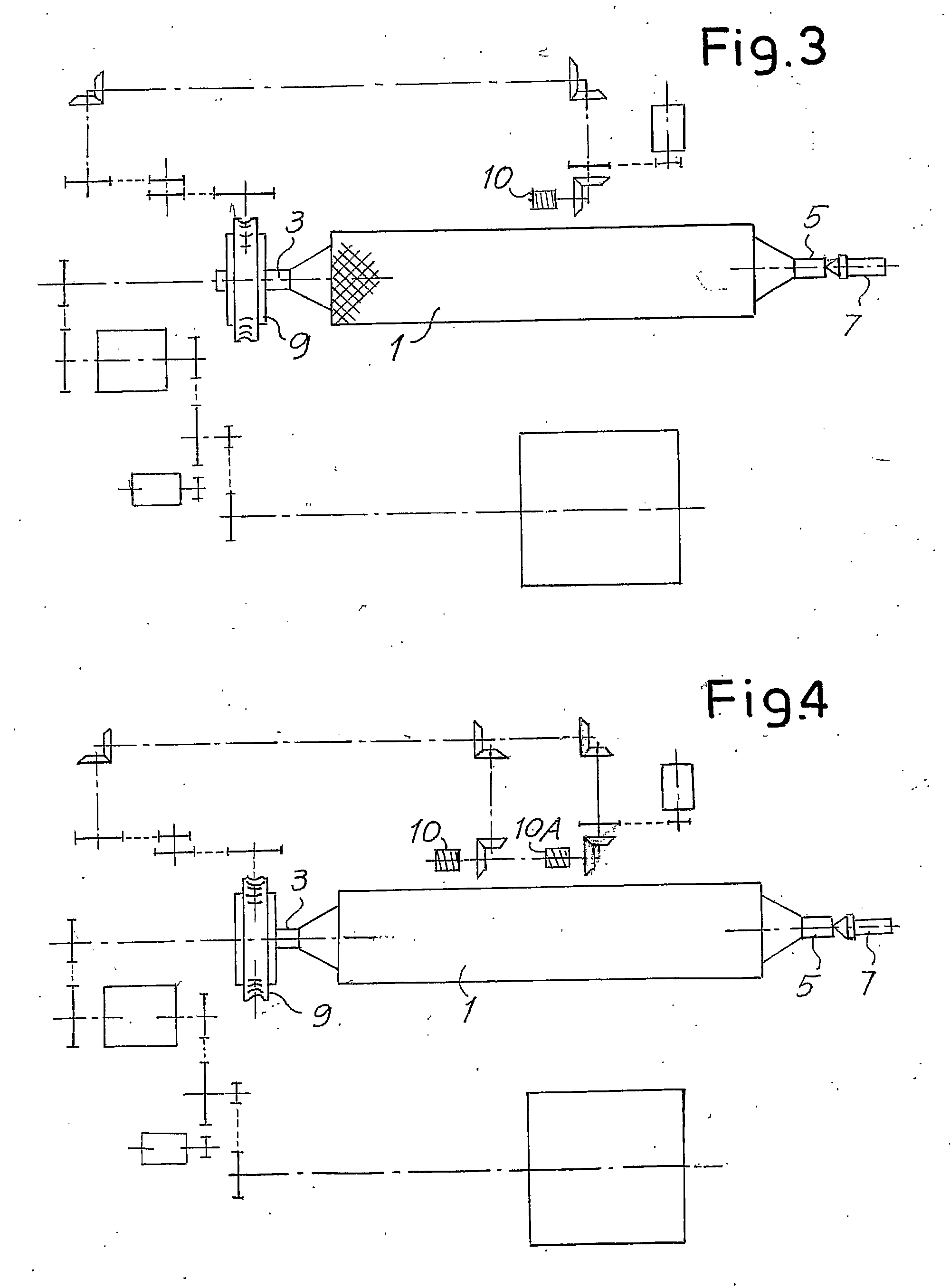
[0054]In order to carry out this incision, the roller 1, which has previously been ground, is set with the shanks 3 and 5 between the tailstock 7 and the spindle of a lathe, to which the spindle is fixed with respect to a gear 9, which imparts the motion of rotation through a gear transmission of a known type. The principal members of the lathe are represented schematically in FIG. 3 and are not described in greater detail, since they are known to those skilled in the art.

[0055]Designated by 10 is a hob that carries out, on the cylindrical surface of the previously ground roller 1, with two or more successive passes and two different inclinations, a double series of helical grooves, which by intersecting with one another generate protuberances having the sha...


PUM

PropertyMeasurementUnit
convex curved shapeaaaaaaaaaa
heightsaaaaaaaaaa
shapeaaaaaaaaaa

Abstract

A method for obtaining an incision in an embossing roller using a hob, with a low-cost technique that enables protuberances that are rounded on top to be obtained, which improve the quality of the embossed material and reduce the wear of the mechanical components of the embossing units. The shape of the protuberances is obtained by machining the cylindrical surface of the roller that is placed between the tailstocks of the lathe using a hob that has teeth, the profile of which in cross-sectional view is complementary to that of the cross-section of the protuberances illustrated in FIG. 6. FIG. 6 shows schematically in cross-sectional view a portion of the surface of the roller with protuberances in the machining step and a portion of the hob with the teeth that are generating the grooves that define the side faces of the protuberances. As seen in FIG. 6A, the grooves between the teeth of the hob have a profile that is curvilinear in a cross-sectional view. With a double pass at two different inclinations of the surface of the roller, the protuberances of FIGS. 5 and 6 are generated.

Description

TECHNICAL FIELD[0001]The present invention relates in general to embossing rollers, and in particular to embossing rollers for manufacturing paper and specifically for embossing so-called “tissue paper”, used for the production of toilet paper, kitchen wipes, paper handkerchiefs and serviettes or similar products.[0002]The invention also relates to an embossing unit comprising one or more embossing rollers and possible pressure rollers.STATE OF THE ART[0003]For processing weblike products, in particular but not exclusively cellulose fibres-based weblike materials, such as paper, tissue paper or crepe paper and the like, so-called embossing units are frequently used, in which the weblike material is subjected to an action of permanent deformation. For this purpose, the weblike material is passed between two embossing rollers or else between an embossing roller and a pressure roller, normally coated with elastically yielding material, such as rubber or the like.[0004]The embossing rol...

Claims


Application Information

Patent Timeline
Patent Type & Authority Applications(United States)
IPC IPC(8): B29C59/04
CPCB23C3/32B23C5/04B23C2210/088Y10T29/49561B31F2201/0717B31F2201/0733B31F2201/0738B31F1/07Y10T29/4956
Inventor GELLI, MAURO
Owner FABIO PERINI SPA
Why Eureka
Try Eureka