Passive cooling and arresting device for molten core material

a technology of molten core material and passive cooling, which is applied in the direction of nuclear elements, greenhouse gas reduction, nuclear engineering problems, etc., can solve the problems of contaminating neighboring soil, affecting the structural integrity of containment buildings, and molten core materials can ablate the concrete structure of reactor cavities, so as to effectively remove the decay heat of molten core materials, the effect of reducing the possibility of steam explosion

Active Publication Date: 2009-05-07
KOREA ATOMIC ENERGY RES INST +1
View PDF14 Cites 15 Cited by
  • Summary
  • Abstract
  • Description
  • Claims
  • Application Information

AI Technical Summary

Benefits of technology

[0014]One object of the present invention is to provide an improved apparatus for passively cooling and retaining molten core material, which can greatly reduce the possibility of steam explosion during the direct interaction between ultrahigh-temperature molten core material and cooling water, can effectively remove the decay heat of the molten core material, and can be assembled in a containment building for both existing nuclear reactors and newly constructed nuclear reactors.Technical Solution

Problems solved by technology

However, when molten core material discharged from a damaged reactor vessel during a severe accident in the nuclear plant is not effectively retained and cooled, the discharged molten core material may ablate the concrete structure of a reactor cavity, contaminate neighboring soil, and threaten the structural integrity of a containment building.
However, the so-constructed conventional apparatus cannot be installed in a containment building for existing nuclear reactors because the containment building must be greatly altered in its compartment structure so as to install the apparatus therein.
Also, the apparatus has a problem in that the ultrahigh-temperature molten core material melts the cooling water retention tank 110 and then reacts directly with the cooling water in the cooling water retention tank 110 thereby to generate steam violently, whereby a steam explosion may undesirably occur.
Accordingly, heat transfer efficiency between the molten core material and the cooling water is not efficient and thus a very large cooling water tank is required.
However, the pump may not be operated when a severe accident occurs in a nuclear plant, whereby the apparatus has low reliability.
Further, the cooling ability of the pump is degraded as time goes on, whereby the decay heat of the molten core material cannot be effectively removed.

Method used


Image

  • Passive cooling and arresting device for molten core material
  • Passive cooling and arresting device for molten core material
  • Passive cooling and arresting device for molten core material

Examples


Embodiment Construction

[0030]Hereinafter, preferred embodiments of the present invention will be described in detail with reference to the attached drawings.

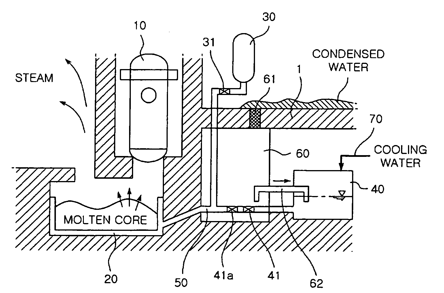
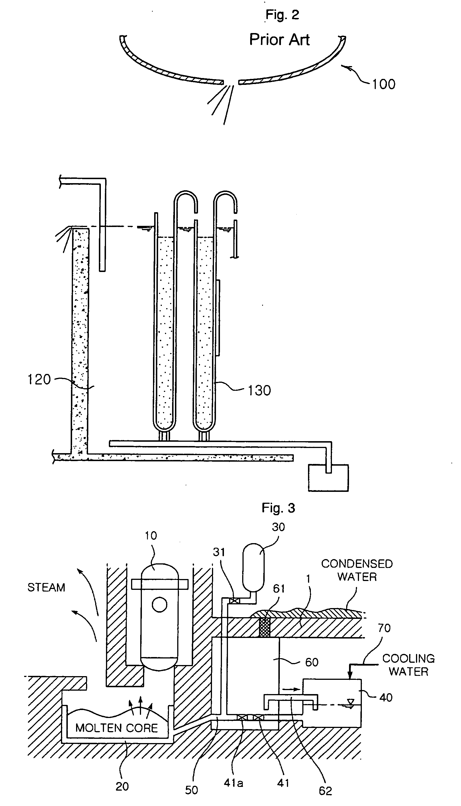
[0031]FIG. 3 is a schematic view of an apparatus for passively cooling and retaining molten core material according to the present invention.

[0032]Referring to FIG. 3, the inventive passive cooling and retaining apparatus cools and retains molten core material from a reactor vessel, and includes a molten core material retention tank 20 installed below a reactor vessel 10 so as to retain molten core material discharged from the reactor vessel 10.

[0033]The molten core material retention tank 20 is configured not only to endure high-temperature molten core material, but also to uniformly provide cooling water for uniformly cooling the high-temperature molten core material. A structure of the molten core material retention tank 20 will be described in detail later with reference to FIGS. 4 through 6.

[0034]As shown in FIG. 3, the inventive passive cooling ...


PUM

PropertyMeasurementUnit
pressureaaaaaaaaaa
refractoryaaaaaaaaaa
temperatureaaaaaaaaaa

Abstract

An apparatus for passively cooling and retaining molten core material discharged from a damaged reactor vessel during a severe accident in the nuclear plant including: a molten core material retention tank to retain molten core material; a compressed gas tank storing high-pressure inert gas; a cooling water storage tank being installed higher than the molten core material retention tank; and a mixing means. The molten core material retention tank includes an outer retention vessel having at least one coolant hole, a porous protection vessel formed at an inside of the outer retention vessel, and a gravel layer formed between the outer retention vessel and the porous protection vessel. The apparatus can be installed in a reactor cavity without changing the compartment structure of a containment building, and makes it possible to prevent a steam explosion during the cooling process for the ultrahigh-temperature molten core material and to secure the reliability of the cooling process.

Description

TECHNICAL FIELD[0001]The present invention relates to an apparatus for passively cooling and retaining molten core material, and more particularly, to an apparatus for passively cooling and retaining molten core material, which can passively cool, solidify and retain ultrahigh-temperature radioactive molten core material, which is discharged from a damaged nuclear reactor vessel during a severe accident in a nuclear plant, in a reactor cavity so as to prevent the discharged molten core material from damaging a neighboring structure, threatening the safety of workers, threatening the integrity of the reactor containment, or contaminating water sources or soil.BACKGROUND ART[0002]Generally, a nuclear plant includes hundreds of systems having separate functions. These systems are roughly classified into a nuclear steam supply system (NSSS) having a nuclear reactor as its main element, a turbine / generator system having a generator driven by supplied steam and other auxiliary equipments....

Claims


Application Information

Patent Timeline
Patent Type & Authority Applications(United States)
IPC IPC(8): G21C9/016
CPCG21C9/016Y02E30/40G21Y2004/302G21Y2002/50Y02E30/30A23L7/10A23P20/20A23P30/25
Inventor SONG, JIN HOKIM, HWAN YEOLMIN, BEONG TAEKIM, HEE DONG
Owner KOREA ATOMIC ENERGY RES INST
Why Eureka
Try Eureka