
Membrane electrode assembly and method for making the same

Inactive Publication Date: 2009-05-07
TSINGHUA UNIV +1
View PDF30 Cites 43 Cited by
  • Summary
  • Abstract
  • Description
  • Claims
  • Application Information

AI Technical Summary

Benefits of technology

[0021]The gas diffusion layer 16 includes a carbon nanotube film. The carbon nanotube film includes a plurality of carbon nanotubes nearly parallel to a surface of the carbon nanotube film. The carbon nanotubes are selected from the group consisting of the carbon nanotubes isotropically arranged, arranged along a fixed direction, or arranged along different directions. The adjacent carbon nanotubes are combined and attracted by van der Waals attractive force, thereby forming a free-standing structure. Due to the carbon nanotube film having a plurality of carbon nanotubes isotropically arranged, arranged along a fixed direction, or arranged along different directions, the carbon nanotube film has good tensile strength, thereby having a free-standing structure. It is understood that the carbon nanotube film is very microporous. Sizes of the micropores are less than 1 micrometer. Length and width of the carbon nanotube film is not limited. It can be made with any desired length or width according to practical needs. In the present embodiment, a thickness of the carbon nanotube film is in an approximate range from 1 micrometer to 1 millimeter.

Problems solved by technology

However, the process of making the carbon fiber paper has the following disadvantages: Firstly, the carbon fibers in the carbon fiber paper are not uniformly dispersed, thereby the gaps therein are uneven resulting in the carbon fibers having a small specific surface area.
Secondly, the carbon fiber paper has high electrical resistance, thus restricting the transfer of electrons between the gas diffusion layer and the external electrical circuit, thereby reducing the reaction activity of the MEA.
Thirdly, the carbon fiber paper has poor tensile strength, and is difficult to process.

Method used


Image

  • Membrane electrode assembly and method for making the same
  • Membrane electrode assembly and method for making the same
  • Membrane electrode assembly and method for making the same

Examples


Embodiment Construction

[0019]Reference will now be made to the drawings, in detail, to describe embodiments of the membrane electrode assembly and the method for making the same.

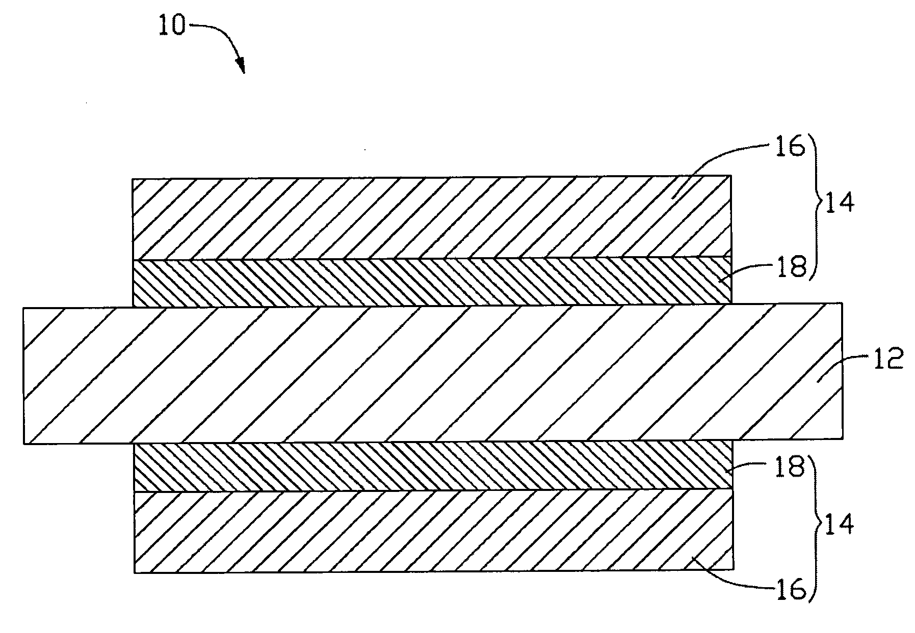
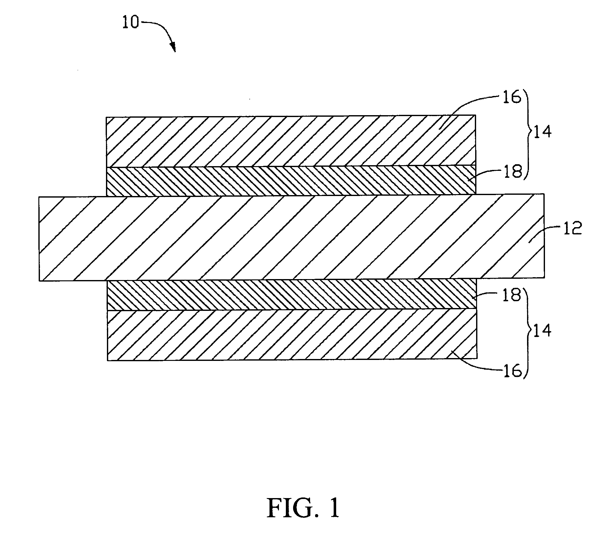
[0020]Referring to FIG. 1, a membrane electrode assembly 10 is provided in the present embodiment. The membrane electrode assembly 10 includes a proton exchange membrane 12 and two electrodes 14. The proton exchange membrane 12 includes two opposite surfaces. The two electrodes 14 are separately disposed on the two opposite surfaces of the proton exchange membrane 12. Further, each of the electrodes 14 includes a catalyst layer 18 and a gas diffusion layer 16. The catalyst layer 18 is configured for being sandwiched between the gas diffusion layer 16 and the proton exchange membrane 12.

[0021]The gas diffusion layer 16 includes a carbon nanotube film. The carbon nanotube film includes a plurality of carbon nanotubes nearly parallel to a surface of the carbon nanotube film. The carbon nanotubes are selected from the group consisting...


PUM


Abstract

The present invention relates to a membrane electrode assembly. The proton exchange membrane includes two opposite surfaces. The two electrodes are separately disposed on the two opposite surfaces of the proton exchange membrane. The two electrodes are separately disposed on two opposite surfaces of the proton exchange membrane. Further, each electrode includes a catalyst layer and a gas diffusion layer. The catalyst layer is configured for being sandwiched between the gas diffusion layer and the proton exchange membrane. The gas diffusion layer includes a carbon nanotube film. The carbon nanotube film includes a plurality of carbon nanotubes, which are selected from the group consisting of the carbon nanotubes isotropically arranged, arranged along a fixed direction, or arranged along different directions. And a method for making the membrane electrode assembly is also included.

Description

[0001]This application is related to a commonly-assigned application entitled, “MEMBRANE ELECTRODE ASSEMBLY AND METHOD FOR MAKING THE SAME”, filed **** (Atty. Docket No. US17021). Disclosure of the above-identified application is incorporated herein by reference.BACKGROUND[0002]1. Field of the Invention[0003]The invention generally relates to membrane electrode assembly and method for making the same and, particularly, to a carbon nanotube based membrane electrode assembly of a fuel cell and method for making the same.[0004]2. Discussion of Related Art[0005]Fuel cells can generally be classified into alkaline, solid oxide, and proton exchange membrane fuel cells. The proton exchange membrane fuel cell has received more attention and has developed rapidly in recent years. Typically, the proton exchange membrane fuel cell includes a number of separated fuel cell work units. Each work unit includes a fuel cell membrane electrode assembly (MEA), flow field plates (FFP), current collecto...

Claims


Application Information

Patent Timeline
IPC IPC(8): H01M8/10B05D5/12
CPCH01M8/0234H01M8/1004H01M8/10Y02E60/521H01M2008/1095Y02P70/50Y02E60/50
Inventor LIU, CHANG-HONGFAN, SHOU-SHAN
Owner TSINGHUA UNIV
Learn More