
Gas sensor control device

a control device and sensor technology, applied in the direction of instruments, specific gravity measurement, mechanical means, etc., can solve the problem of increasing the cost of the gas sensor control device, and achieve the effect of improving the accuracy of detecting concentration

Active Publication Date: 2009-05-14
NGK SPARK PLUG CO LTD
View PDF7 Cites 11 Cited by
  • Summary
  • Abstract
  • Description
  • Claims
  • Application Information

AI Technical Summary

Benefits of technology

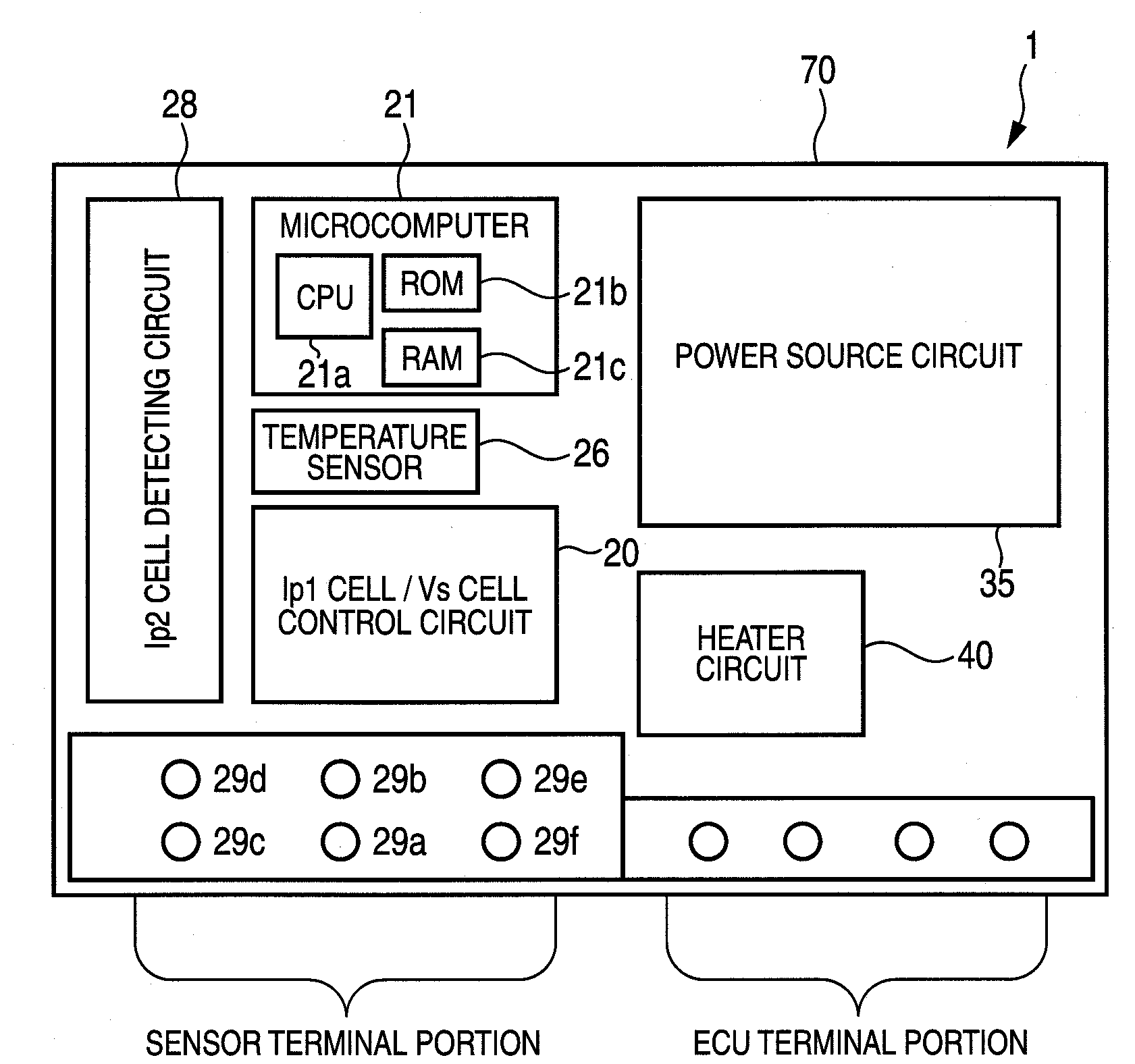
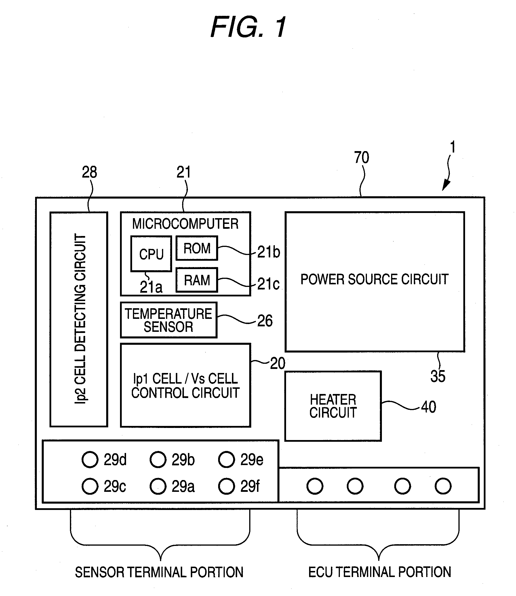
[0011]The present invention was made in consideration of the above circumstances, and an object thereof is to provide a gas sensor control device capable of improving the detection precision of the concentration of a specific gas component even when a characteristic of a voltage control unit mounted on a circuit board for maintaining a cell at a constant voltage changes with a change in temperature of the circuit board.

Problems solved by technology

However, since it is necessary to provide a plurality of voltage correcting units corresponding to the number of voltage control units, the cost of the gas sensor control device increases.

Method used


Image

  • Gas sensor control device
  • Gas sensor control device
  • Gas sensor control device

Examples


first embodiment

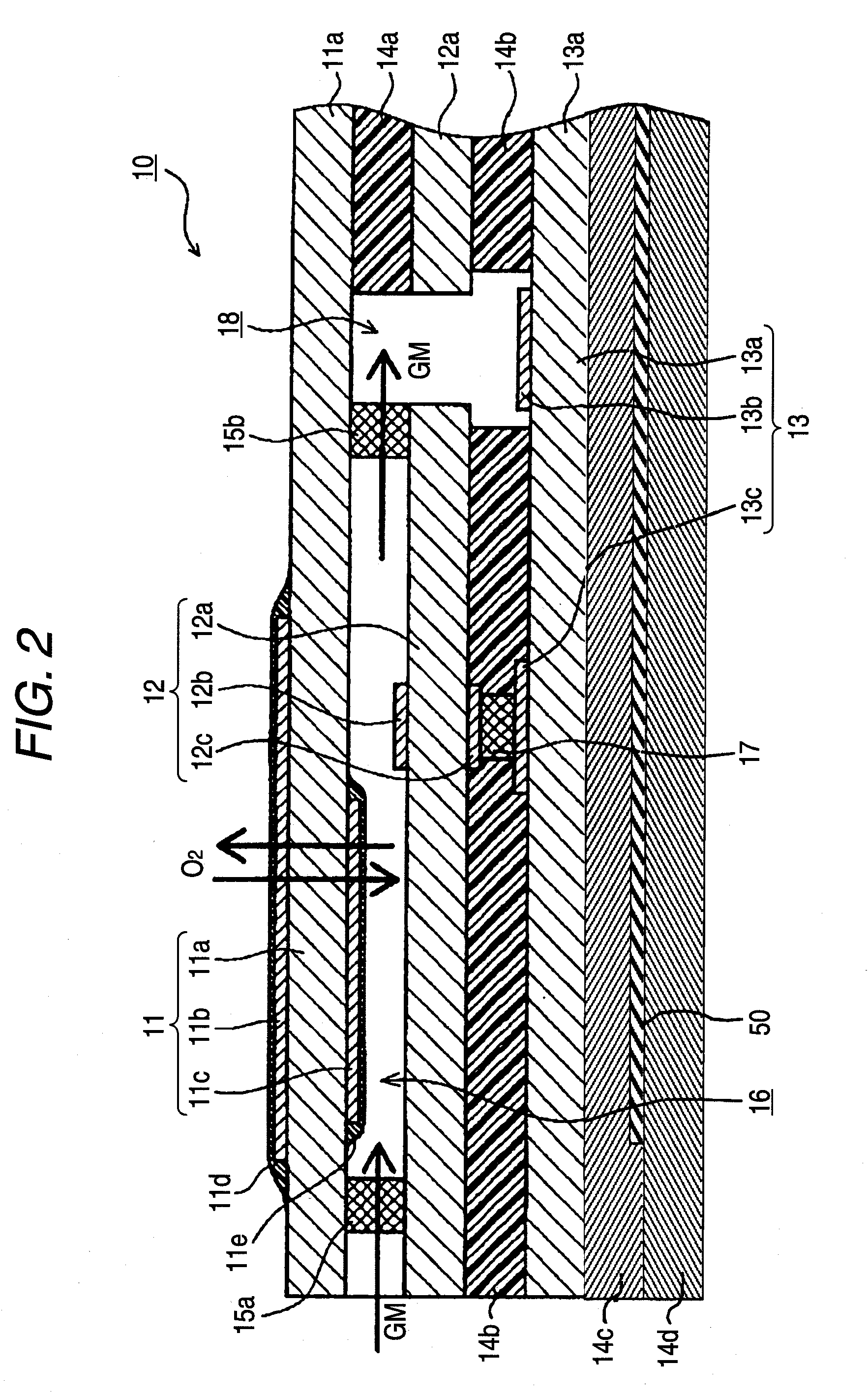
[0074]In this case, a temperature compensation may be carried out so that the inter-terminal voltages of the oxygen concentration detecting cell 12 and the second pumping cell 13 are maintained at the constant voltages V1 and V2, respectively, but the configuration of such a circuit is complicated. Accordingly, in the first embodiment, a temperature compensation is carried out so that the inter-terminal voltage difference (Vp−Vs) between the control target cells (the oxygen concentration detecting cell 12 and the second pumping cell 13) is maintained constant.

[0075]Particularly, in the NOx sensor element 10 according to the first embodiment, since the second pump current Ip2 flowing to the second pumping cell 13 depending on the concentration of the NOx is minute current (e.g., on the order of μAs), if the voltage (i.e., the inter-terminal voltage Vp) applied to the second pumping cell 13 is directly corrected, a not insignificant level of variation may result in response to correct...

second embodiment

[0097]In the second embodiment, a temperature correction is carried out such that the inter-terminal voltage Vs is maintained equal to the inter-terminal voltage (425 mV) at a reference temperature (25° C.).

[0098]The present invention is not limited to the above-described embodiments, but various modifications and changes may be made within the scope and spirit of the claims appended hereto. For example, in the above embodiments, the Vs correction values is stored in the map for each of the predetermined temperature ranges, but the Vs correction values may be stored in the map for each degree of temperature. Further, in the above-described embodiments, the NOx sensor element includes three solid electrolyte layers but may include only two layers. An NOx sensor element including two solid electrolyte layers is disclosed, for example, in U.S. Pat. No. 5,942,190 (FIG. 2 and accompanying description) incorporated herein by reference.

[0099]The present invention is applicable to a gas sen...


PUM


Abstract

A gas sensor control device for controlling a gas sensor, the gas sensor including a gas sensor element that includes a cell including a pair of electrodes and a solid electrolyte, the gas sensor control device including a circuit board connectable to the gas sensor. The circuit board has mounted thereon a voltage control unit mounted on the circuit board and configured to control a voltage developed across a pair of electrodes of the cell to a constant voltage; a temperature detecting unit mounted on the circuit board and configured to detect a temperature of the circuit board; and a voltage correcting unit mounted on the circuit board and configured to apply a correction voltage to the voltage control unit compensating for a temperature-dependent variation in the constant voltage based on the temperature detected by the temperature detecting unit.

Description

BACKGROUND OF THE INVENTION[0001]1. Field of the Invention[0002]The present invention relates to a gas sensor control device used for controlling a gas sensor. The gas sensor includes a gas sensor element configured to detect the concentration of a specific gas component in an exhaust or combustion gas of a combustor, an internal-combustion engine, etc.[0003]2. Description of the Related Art[0004]An air-fuel ratio sensor or an oxygen sensor for detecting concentration of oxygen in exhaust gas is known as a gas sensor for controlling combustion or improving fuel efficiency of an internal-combustion engine of a vehicle. In addition, in response to the need for reducing the amount of nitrogen oxide (NOx) in exhaust gas so as to meet strict exhaust gas regulations of a vehicle, an NOx sensor capable of directly measuring concentration of NOx has been developed.[0005]This kind of gas sensor includes a gas sensor element including one or more cells each including an oxygen ion conductive ...

Claims


Application Information

Patent Timeline
IPC IPC(8): G01N29/02
CPCG01N27/4175
Inventor ISHIGURO, YASUHIROABE, SATORUKOBAYASHI, AKIHIROSUMI, TAKAYUKI
Owner NGK SPARK PLUG CO LTD
Learn More