

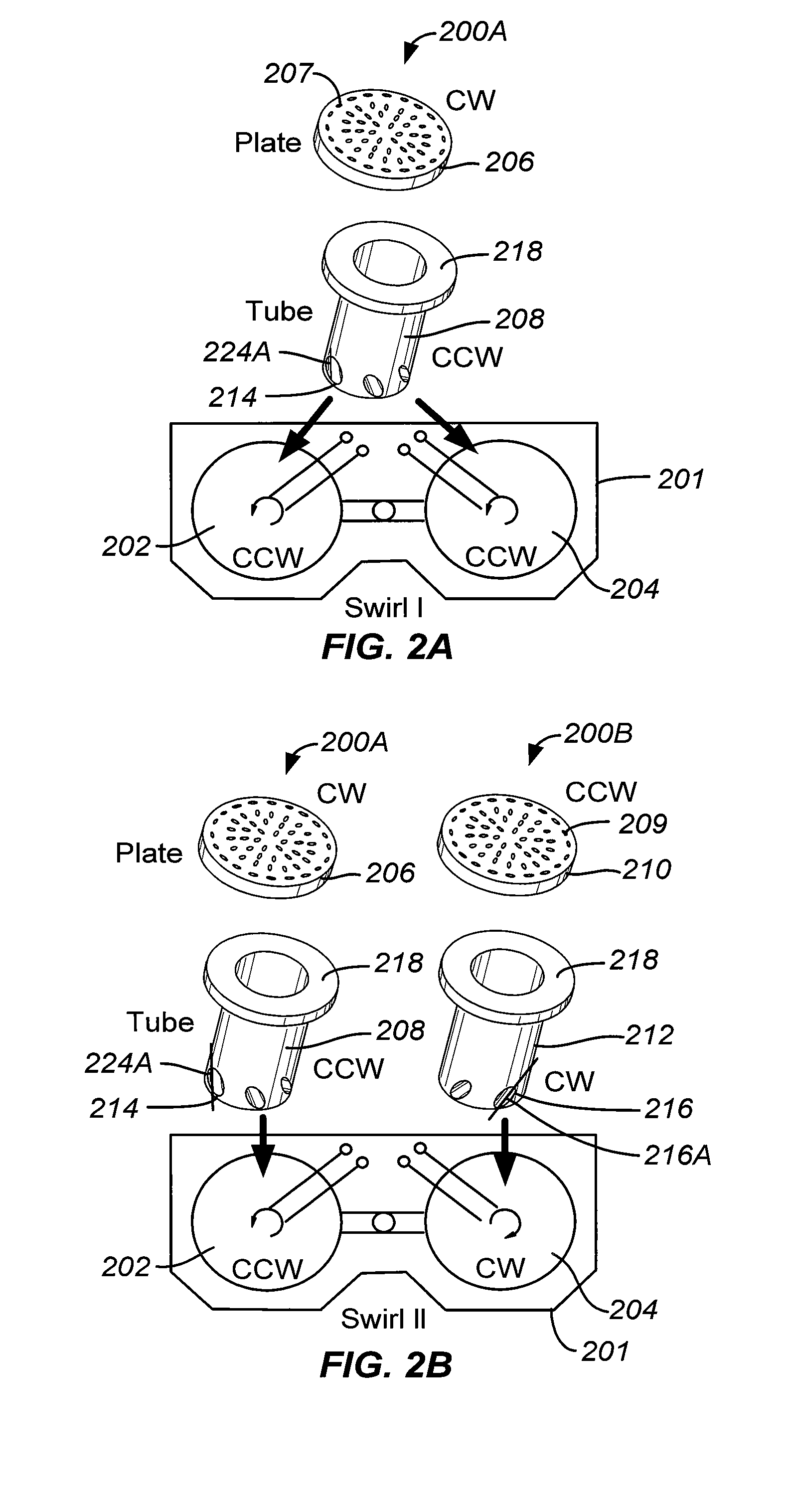
Gas mixing swirl insert assembly
a technology of inserts and swirls, which is applied in the directions of liquid transfer devices, transportation and packaging, packaging, etc., can solve the problems of variable sheet resistance, degrade device performance, and increase the sensitiveness of cvd processes to gas flow and mixture parameters, so as to increase the mixing extent
- Summary
- Abstract
- Description
- Claims
- Application Information
AI Technical Summary
Benefits of technology
Problems solved by technology
Method used
Image

Examples
Embodiment Construction
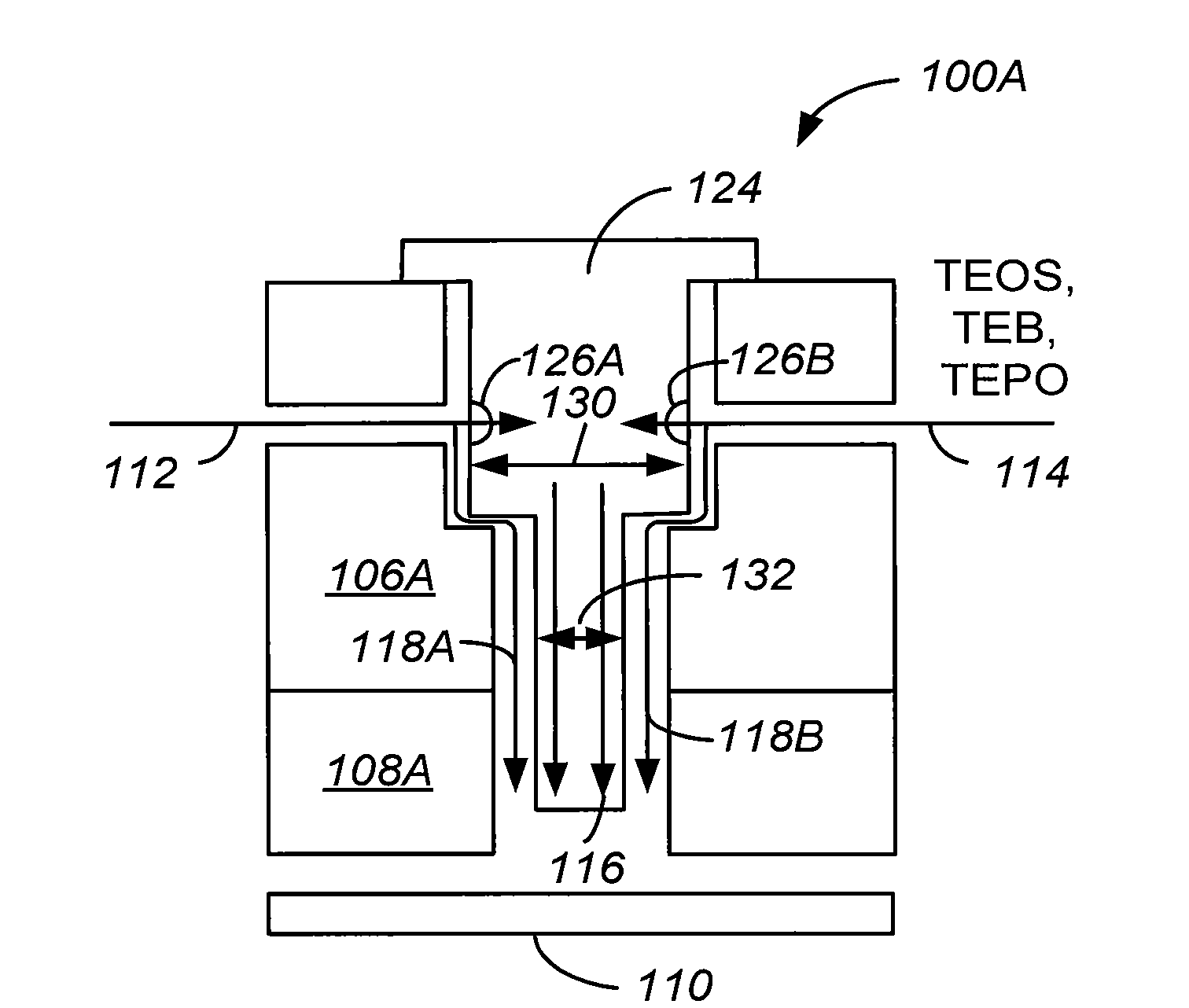
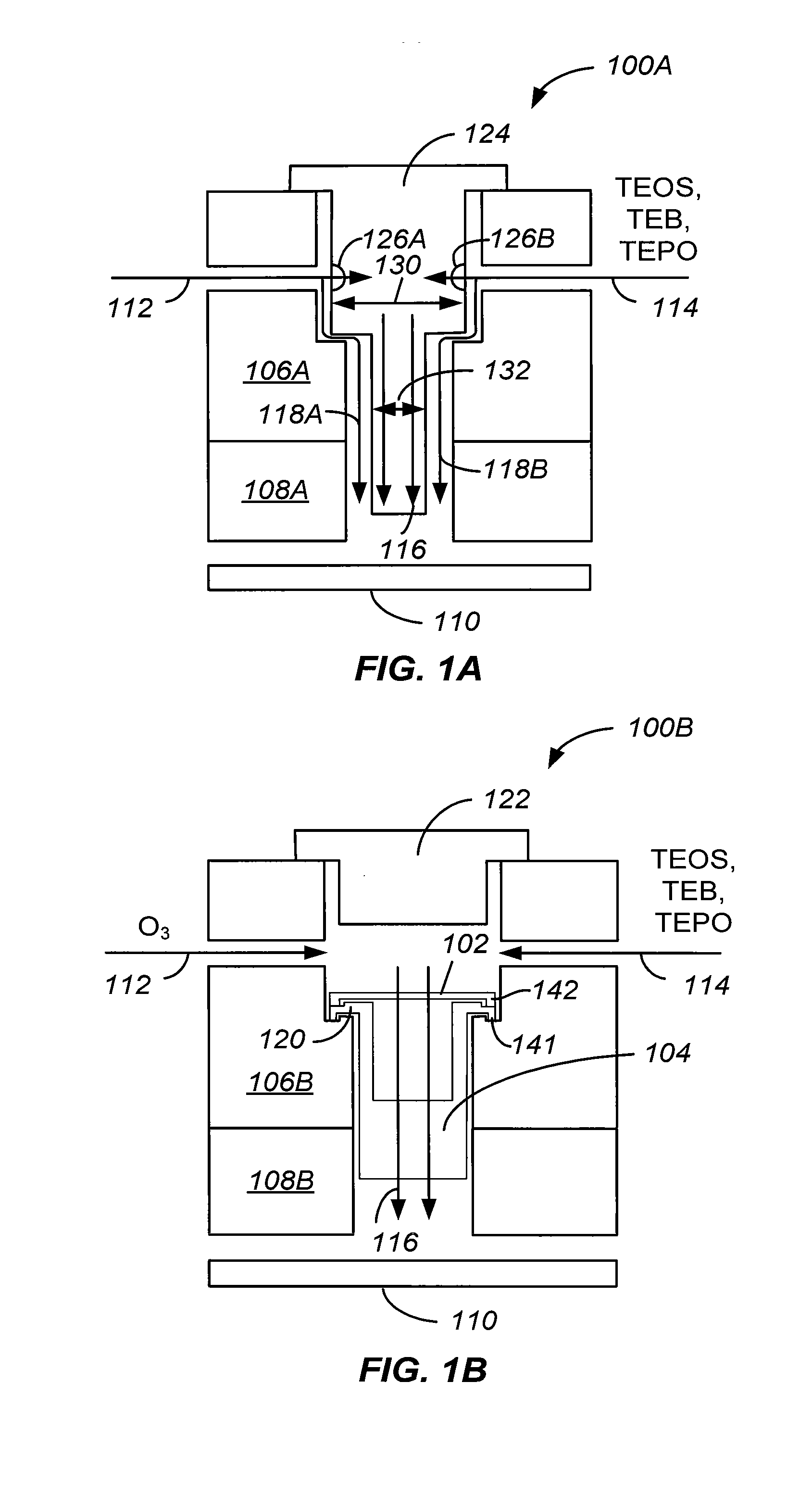
[0024]Chamber Left-to-Right matching issues for dielectric film depositions in processing, such as a two-step boron-phosphate silicate glass (BPSG) deposition within a sub-atmospheric chemical vapor deposition (SACVD) chamber, may cause significant wafer side-to-side variation in thickness. This uneven side-to-side matching may be caused by multiple factors, such as variation in gas mixing, uneven delivery of gas / vapor, and heater leveling or lift to sides. These problems may be addressed with swirl mixing inserts, automatic flow splitters, and / or dual-pressure heater lifts designed for thorough gas mixing and uniform distribution in vapor delivery, as well as accurate spacing in heater leveling.
[0025]FIG. 1A illustrates a cross-sectional view of a standard mixing insert. The standard mixing insert 100A includes a mixing block 106A coupled to a gas box 108A, a mixing insert 124, and a blocker plate 110. A first process gas such as O3 may flow into the mixing block 106A from a pipeli...
PUM
| Property | Measurement | Unit |
|---|---|---|
| pressures | aaaaa | aaaaa |
| pressures | aaaaa | aaaaa |
| diameter | aaaaa | aaaaa |
Abstract
Description
Claims
Application Information