Cooling apparatus for a computer system

a technology of cooling apparatus and computer system, which is applied in the direction of lighting and heating apparatus, instruments, machines/engines, etc., can solve the problems of the reduction in the energy consumption of the computer system, and achieve the effect of efficient, versatile and effective use of waste hea

Inactive Publication Date: 2009-05-14
FUJITSU SIEMENS COMP GMBH
View PDF9 Cites 16 Cited by
  • Summary
  • Abstract
  • Description
  • Claims
  • Application Information

AI Technical Summary

Benefits of technology

[0003]The purpose of the invention is to create a cooling apparatus for a computer system, and a method for cooling at least one heat producing component of a computer system, which enables an effective cooling and an efficient and versatile use of waste heat from a computer system.
[0005]For the cooling apparatus, evaporation of the working medium achieves an effective heat absorption, which brings about good cooling properties. In the cooling apparatus, the absorbed heat can be converted in a thermodynamic cycle of the heat engine into mechanical energy, which is usable in manifold ways. For example, a steam turbine having a generator for converting the mechanical energy into electrical power can be employed, and the electrical power can be used to cover a portion of the primary power requirement of the computer system. It also is possible to couple the steam turbine to cooling medium compressors that are used in an air-conditioning system. Air-conditioning systems frequently are used to provide climate control of rooms for computer systems. If a portion of the energy / power required for operating the air-conditioning system is supplied by making useful the waste heat of the computer system, this in turn leads to a decrease in the energy consumption connected with operation of the computer system.
[0008]Heat absorbed in the evaporator can be used for cooling purposes in the cooling apparatus by means of the thermodynamic cycle of the absorption refrigerator. For example, an air-conditioning system can be operated or supported in order to provide climate control for the rooms of the computer system, effectively lowering the primary power requirement connected with operation of the computer system.

Problems solved by technology

If a portion of the energy / power required for operating the air-conditioning system is supplied by making useful the waste heat of the computer system, this in turn leads to a decrease in the energy consumption connected with operation of the computer system.

Method used


Image

  • Cooling apparatus for a computer system
  • Cooling apparatus for a computer system
  • Cooling apparatus for a computer system

Examples


Embodiment Construction

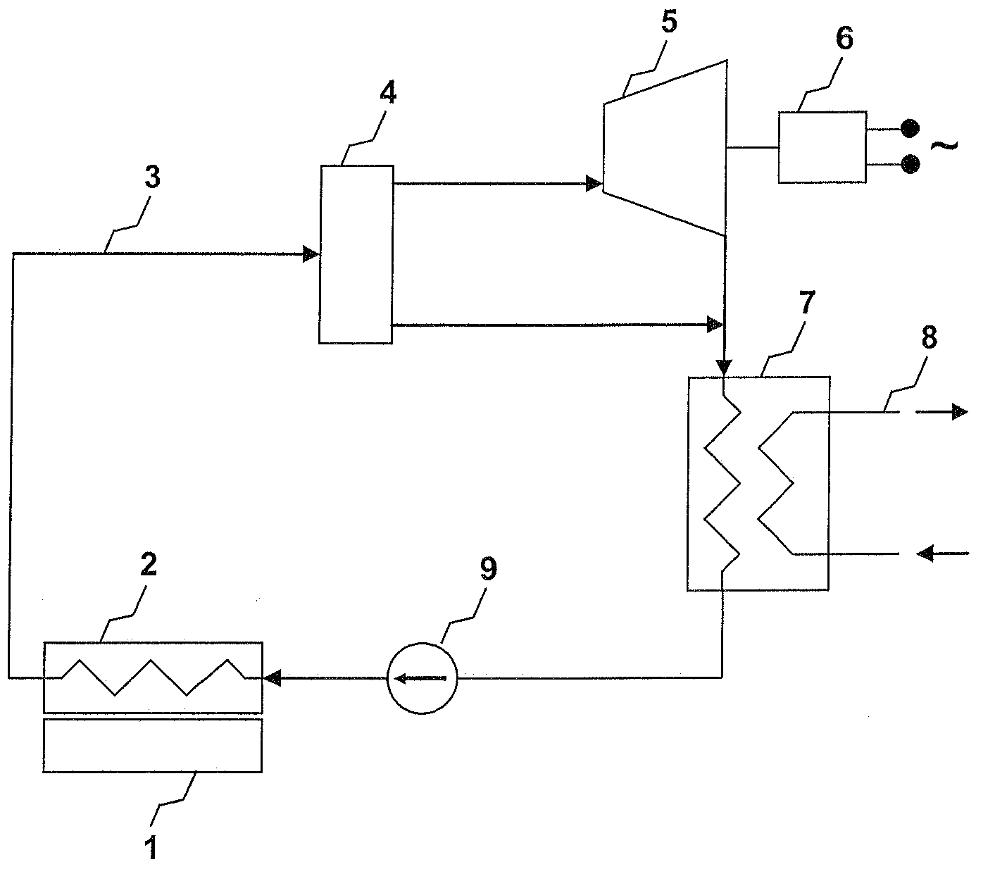
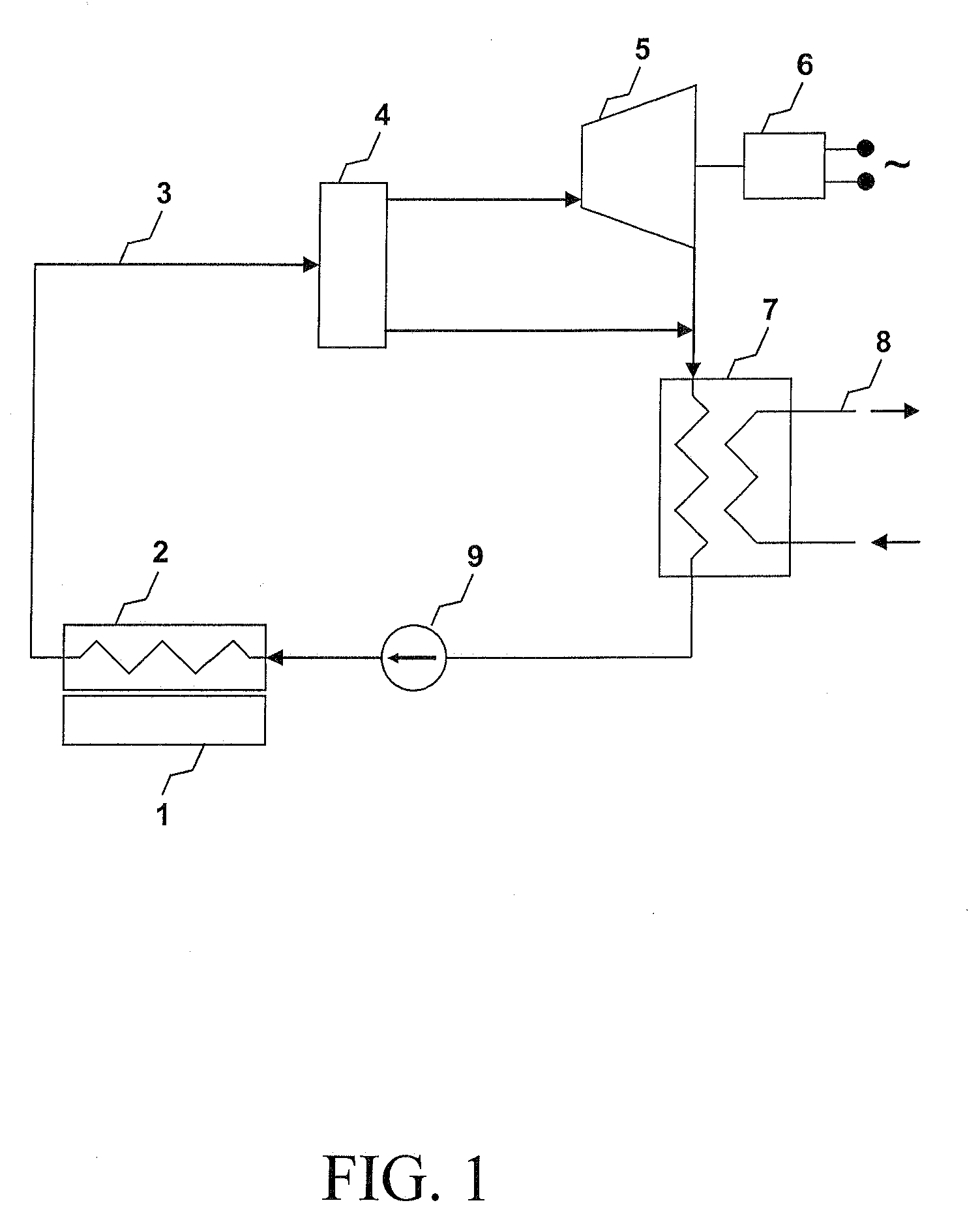
[0016]For the cooling apparatus depicted in FIG. 1, a processor 1 is in direct thermal contact with an evaporator 2. The evaporator 2 is connected by means of a working medium circuit 3, to a separator 4. A first outlet of the separator 4 is connected to a steam turbine 5, which is coupled to a generator 6. A low-pressure outlet of the steam turbine 5 and a second outlet of the separator 4 are led to a condenser 7 that is tied to a cooling-water flow 8. The outlet of the condenser 7 is connected to the evaporator 2 by means of a condensate pump 9.

[0017]During operation of the cooling apparatus shown in FIG. 1, waste heat from a heat producing component of the computer system, here, by means of example, the processor 1, is absorbed by the evaporator 2. The evaporator 2 is in direct thermal contact with the processor 1 for this purpose. To this end, it works to advantage for the evaporator 2 to feature a contact surface with the processor 1 and mounting elements corresponding to the s...


PUM


Abstract

The invention relates to a cooling apparatus for a computer system and a method for cooling at least one heat producing component of a computer system.The cooling apparatus for the computer system features an evaporator (2) for a working medium, which can be thermally coupled to the at least one heat producing component of the computer system. In this connection, the cooling apparatus is constructed as a heat engine or as an absorption refrigerator in order to carry out a thermodynamic cycle.

Description

BACKGROUND OF THE INVENTION[0001]The invention relates to a cooling apparatus for a computer system and to a method for cooling at least one heat producing component of a computer system.[0002]Today's computer systems, for example, so-called server farms, can already feature up to several thousand processors. In light of increasing demand on network services, a continuing rise in the number of processors in future systems is foreseeable. In addition, the increasing capacity of individual processors is accompanied by a rise in the electric power required. Taken together, on the one hand this results in an enormous primary power requirement (power consumption) of large computer systems, and on the other hand in a large quantity of waste heat, which must be transported away from the computer system by means of suitable cooling apparatuses, wherein it is known to employ waste heat for heating purposes or for hot water production and thus to render this useful.SUMMARY OF THE INVENTION[00...

Claims


Application Information

Patent Timeline
Patent Type & Authority Applications(United States)
IPC IPC(8): F28D15/00
CPCF01K15/00F01K25/10H05K7/20827G06F2200/201G06F1/20
Inventor KONIG, CHRISTOPH
Owner FUJITSU SIEMENS COMP GMBH
Why Eureka
Try Eureka