Magnetic coupler

Active Publication Date: 2009-05-14
TDK CORPARATION
View PDF11 Cites 20 Cited by
  • Summary
  • Abstract
  • Description
  • Claims
  • Application Information

AI Technical Summary

Benefits of technology

[0018]According to the first and second magnetic couplers of an embodiment of the invention, each yoke is disposed at a position at which the yoke is adjacent to a magnetoresistive element in a radial direction of a thin film coil, which suppresses reduction in intensity of an induced magnetic field generated by the thin film coil, so that the induced magnetic field can be efficiently applied to the magnetoresistive element. Accordingly, even if a smaller current is flowed into the thin film coil

Problems solved by technology

However, significant aging deterioration occurs in the photo-coupler, including deterioration due to consumption of a light emitting diode (LED), or reduction in current transmission rate, in addition, significant delay in signal transmission.
On the other hand, since the pulse tra

Method used


Image

  • Magnetic coupler
  • Magnetic coupler
  • Magnetic coupler

Examples


first embodiment

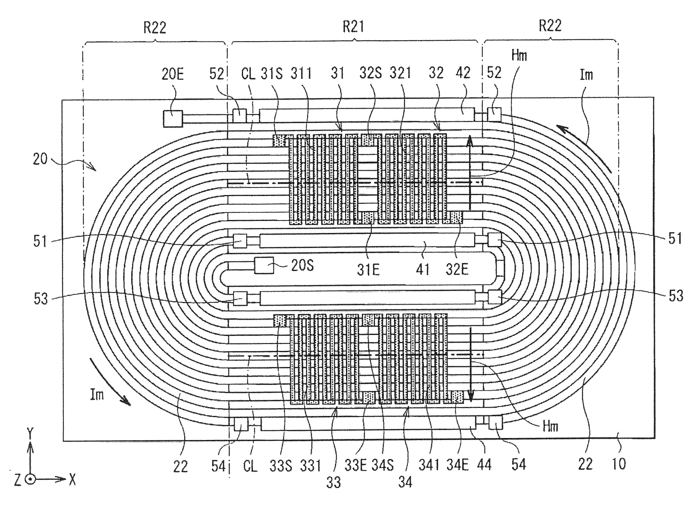
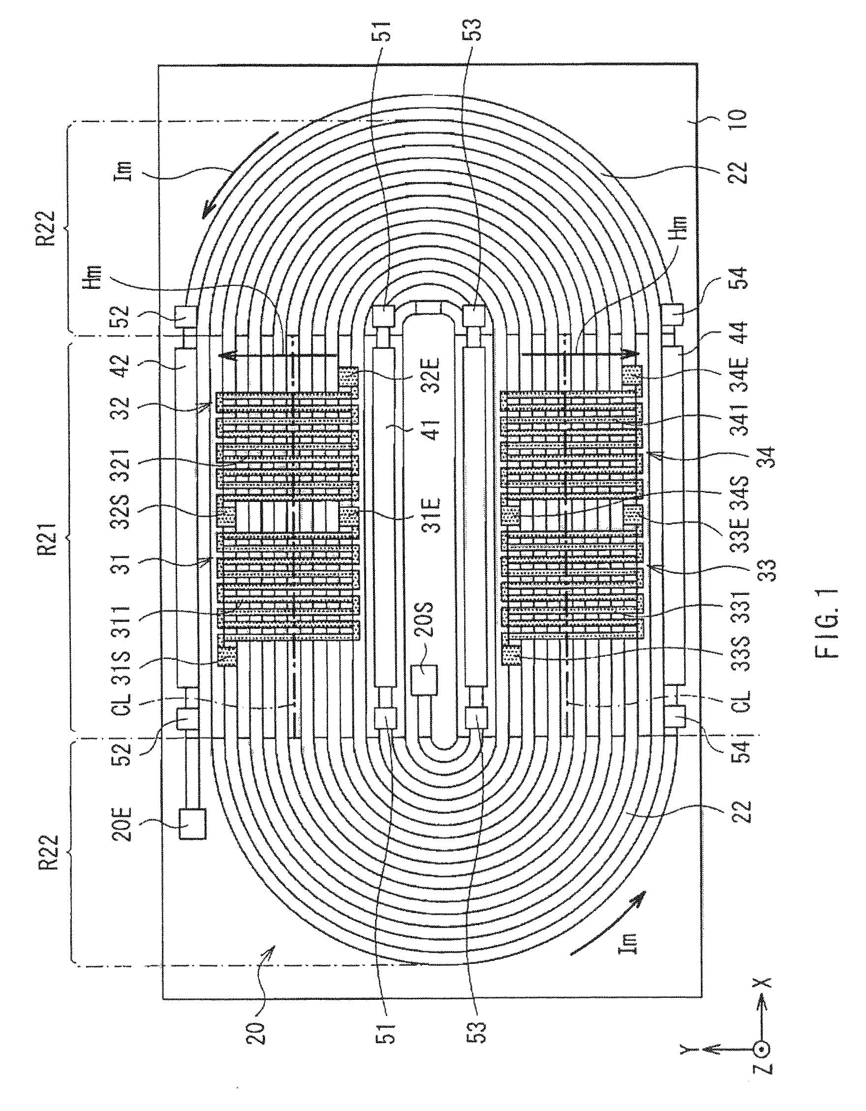
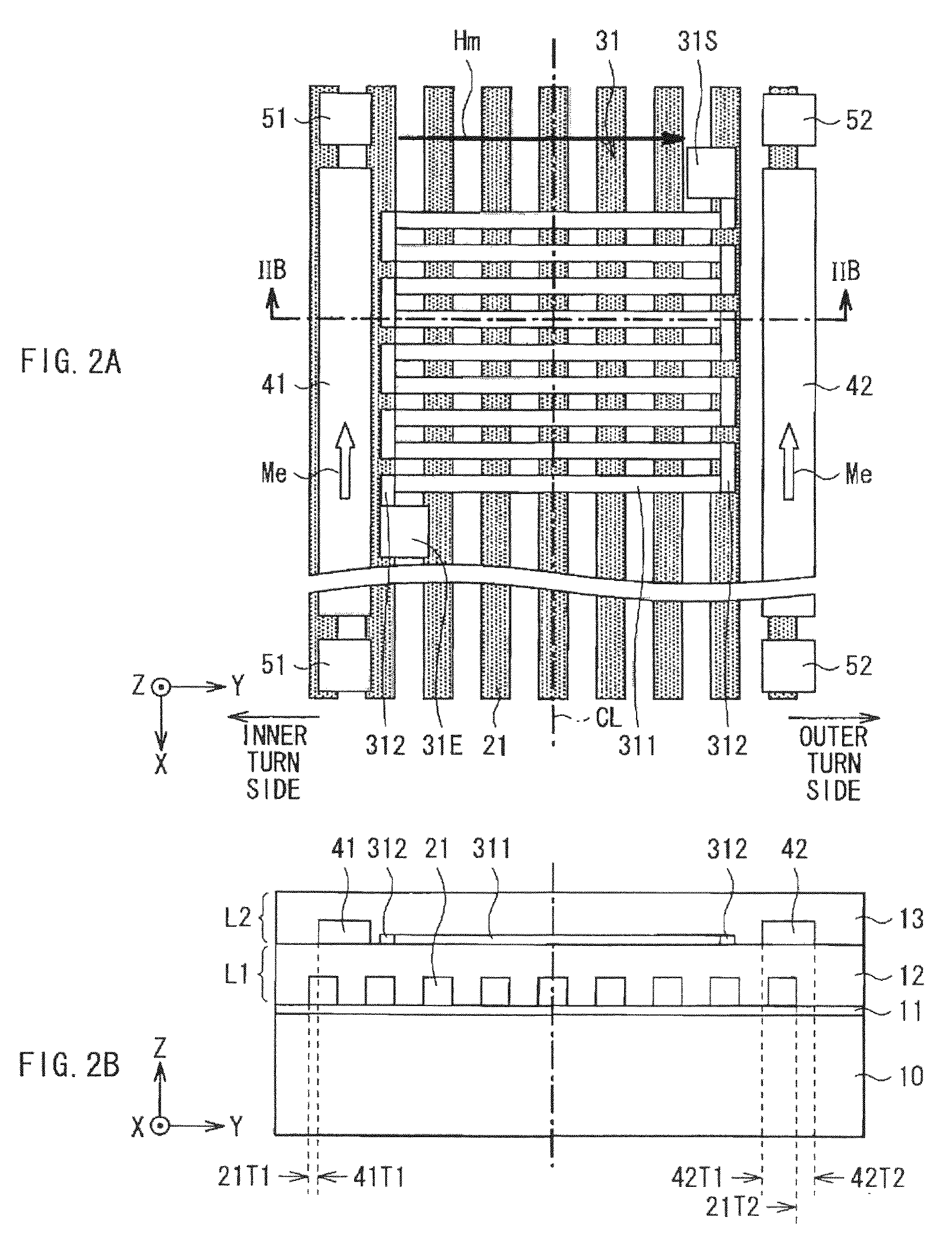
[0034]First, a configuration of a magnetic coupler as a first embodiment of the invention is described with reference to FIG. 1 and FIGS. 2A to 2B. FIG. 1 shows a plan view showing a configuration of the magnetic coupler of the embodiment. FIG. 2A shows an enlarged plan view of a relevant part of the magnetic coupler shown in FIG. 1. FIG. 2B shows a section view seen in an arrow direction along a line IIB-IIB in FIG. 2A. An arrow direction of a signal current Im and an arrow direction of an induced magnetic field Hm indicate relative directions to magnetoresistive elements 31 to 34 (described later) respectively. The magnetic coupler is a device for transmitting a signal from an electric circuit to another electric circuit in an electrically contactless manner, and is an effective unit for cutting noises while transmitting a necessary signal.

[0035]As shown in FIG. 1, the magnetic coupler of the embodiment includes a thin film coil 20 wound in a first layer L1 (FIG. 2B) extending alo...

second embodiment

[0063]Next, a magnetic coupler as a second embodiment of the invention is described with reference to FIGS. 5A to 5B and FIG. 6. FIG. 5A shows a planar configuration of a relevant part (periphery of the first MR element 31) of the magnetic coupler of the embodiment, and is corresponding to FIG. 2A in the first embodiment. FIG. 5B shows a section view seen in an arrow direction along a line VB-VB in FIG. 5A, and is corresponding to FIG. 2B in the first embodiment.

[0064]In the magnetic coupler, unlike the magnetic coupler of the first embodiment, the strip-shaped patterns 311, 321, 331 and 341 included in the first to fourth MR elements 31 to 34 extend in the X-axis direction rather than the Y-axis direction. In the strip-shaped patterns 311, 321, 331 and 341, as shown in FIG. 6, magnetization J61 of the pinned layer 61 is oriented in a +Y direction, and magnetization J63 of the free layer 63 in a no-load state is oriented in a −X direction.

[0065]Even in the magnetic coupler of the em...

examples

[0066]Specific examples of an embodiment of the invention are described.


PUM


Abstract

A magnetic coupler having higher response is provided. The magnetic coupler includes a thin film coil wound in a first layer; a first MR element being disposed in a second layer, and detecting an induced magnetic field generated by a signal current flowing through the thin film coil; and yokes being disposed close to the first MR element, and including a soft magnetic material. The first MR element is disposed in a position corresponding to a linear region of the thin film coil in a stacking direction. The yokes are disposed at both of an inner turn side and an outer turn side of the thin film coil in a manner of interposing the first MR element in the second layer. Thus, reduction in intensity of the induced magnetic field is suppressed, and intensity distribution of the induced magnetic field becomes flatter.

Description

CROSS REFERENCES TO RELATED APPLICATIONS[0001]The present invention contains subject matter related to Japanese Patent Application JP 2007-284507 filed in the Japanese Patent Office on Oct. 31, 2007, the entire contents of which being incorporated herein by reference.BACKGROUND OF THE INVENTION[0002]1. Field of the Invention[0003]The present invention relates to a magnetic coupler having a thin film coil and magnetoresistive elements, and performing signal transmission in a contactless manner between a plurality of electric circuits isolated from one another.[0004]2. Background Art[0005]As a device for transmitting a signal in a contactless manner from one electric circuit to the other circuit among a plurality of electric circuits isolated from one another, a photo-coupler or a pulse transformer has been known in the past. However, significant aging deterioration occurs in the photo-coupler, including deterioration due to consumption of a light emitting diode (LED), or reduction in...

Claims


Application Information

Patent Timeline
IPC IPC(8): H01F17/02
CPCG01R33/09H01F38/14H01F5/003G01R33/091
Inventor HARATANI, SUSUMUYAMAGUCHI, HITOSHI
Owner TDK CORPARATION
Why Eureka
Try Eureka