Antenna

a technology of antennas and antennas, applied in the field of antennas, can solve the problems of complex cable wiring and cumbersome antenna construction, and achieve the effects of reducing the adjusting time, facilitating setting, and large free-range antenna installation

Inactive Publication Date: 2009-05-14
YAGI ANTENNA
View PDF9 Cites 12 Cited by
  • Summary
  • Abstract
  • Description
  • Claims
  • Application Information

AI Technical Summary

Benefits of technology

[0039]In accordance with the present invention, since the plate-shaped radiating element is used so as to form a non-directional antenna, while the plate-shaped radiating element is formed by bending the metal plate having the substantially rectangular shape in either a polygonal shape larger than, or equal to a quadrangle shape or a circular shape, the shape of the cover for the antenna can be made of a cylindrical shape whose length on the side of the polarization plane is shorter than the length thereof on the side of the intersecting polarization plane. As a result, the installation space in the case that the antenna is used as the indoor-purpose antenna can be very small, as compared with that for the conventional indoor-purpose antenna, so that the freedom degree of the antenna installation is large, and the antenna can be easily set even in a narrow place.
[0040]Also, since the directivity of the horizontal plane is an omnidirectional characteristic, it is no longer to rotate the antenna so as to adjust the reception characteristic, so that the adjusting time can be largely reduced. Also, since the antenna characteristic is designed as the omnidirectional characteristic, the antenna can easily receive reflected waves, and even when the direct wave direction of the antenna is shielded, since the antenna receives the reflected waves, it is possible to avoid lowering of the reception level.
[0041]Furthermore, in such a case that the indoor-purpose antenna is installed beside a television receiver, the antenna can achieve the reception performance which is not influenced by the electromagnetic wave environment; the direction of the television receiver can be made coincident with the direction of the antenna, so that the good appearance thereof can be maintained. Moreover, a change in the directivity occurred when a person approaches the antenna can be decreased, so that the lowering amount of the reception level can be reduced, as compared with that of the conventional antenna having the single directivity characteristic.

Problems solved by technology

As previously described, in such a case that electric magnetic waves whose traveling directions are different from each other depending upon broadcasting stations are received by employing single directivity antennas, a plurality of such single directivity antennas must be installed, and thus, antenna constructions are very cumbersome, for instance, mixers are installed, and cable wirings become complex.

Method used


Image

  • Antenna
  • Antenna
  • Antenna

Examples


first embodiment

MODE

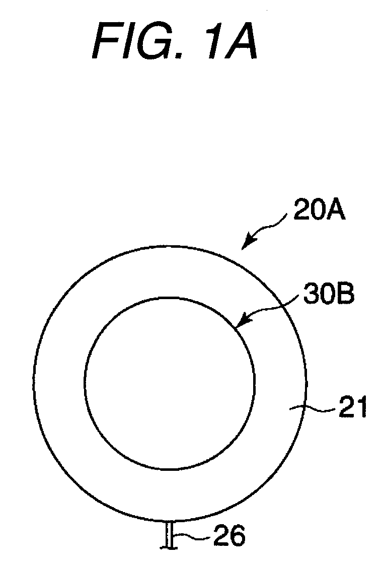
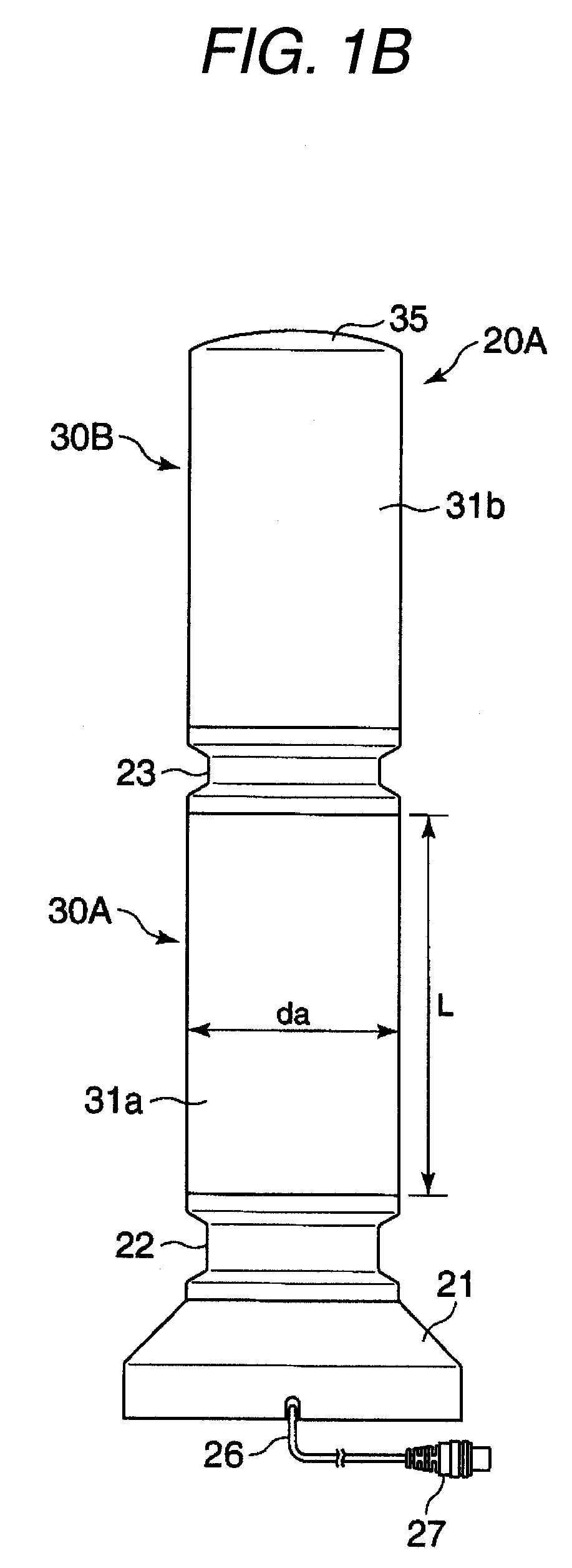
[0044]In an indoor antenna 20A shown in FIG. 1A to FIG. 1C, reference numeral 21 indicates a base which is made of, for example, a synthetic resin and is formed in, for instance, a circular shape. A first antenna main body 30A is mounted via a supporting cylinder 22 on the base 21, and a second antenna main body 30B is mounted via another supporting cylinder 23 on the first antenna main body 30A.

[0045]A diameter of the base 21 is set to approximately 0.22λ (=about 140 mm). A bottom plate 24 is detachably provided on the base 21 by employing, for instance, screws, into which a mixing board 25 is arranged. A mixing circuit for mixing a reception signal of the first antenna main body 30A with another reception signal of the second antenna main body 30B is provided on the mixing board 25. A mixed output of this mixing circuit is conducted via an output cable 26 to an external portion of the base 21. An output-purpose connecting stopper 27 is attached to a tip portion of the output c...

second embodiment

MODE

[0052]The above-described first embodiment mode is described such a case that while the antenna covers 31a and 31b are separately provided with respect to the first antenna main body 30A and the second antenna main body 30B, these antenna covers 31a and 31b are coupled to each other by employing the supporting cylinder 23. In a second embodiment mode of the present invention shown in FIG. 2A and FIG. 2B, an antenna main body 30 is protected by a single antenna cover 31. This antenna cover 31 is fixed by a screw 313 at a center portion thereof, while cover elements 311 and 312 formed in, for example, semi-cylindrical shapes are joined to each other. Also, the antenna cover 31 is formed by inclining an upper edge unit.

[0053]While a lower edge portion of the antenna cover 31 is made in a small diameter, the antenna main body 30 is detachably provided on a base 21a. It should also be noted that in the second embodiment mode, the mixing board 25 is provided on the side of the antenna...

third embodiment

MODE

[0056]A third embodiment mode of the present invention shown in FIG. 3, FIG. 4A, and FIG. 4B constitutes an indoor and outdoor commonly-used antenna 20D by utilizing the antenna main body 30 represented in the second embodiment mode. In this indoor and outdoor commonly-used antenna 20D, an indoor setting-purpose base 21a and an outdoor setting-purpose base 21c are detachably are provided with respect to the antenna main body 30. For instance, while a structure between the antenna main body 30 and the bases 21a, 21c is formed as a locking type structure, the indoor setting-purpose base 21a and the outdoor setting-purpose base 21c are pivotably rotated at a predetermined angle so as to be detachably attached to the antenna main body 30.

[0057]Then, a connecting stopper 43 is provided at a center of the lower edge portion of the antenna main body 30, another connecting stopper41 is provided at an inside center of the base 21a, and when the antenna main body 30 is mounted on the base...


PUM


Abstract

A plate-shaped radiating element of a shape having at least three planes is formed by bending a metal plate having a substantially rectangular shape. A first slit is provided from a lower edge of the plate-shaped radiating element up to a portion in the vicinity of an upper edge of the plate-shaped radiating element while passing through a center point of the plate-shaped radiating element, and forms plate-shaped dipole elements on both sides thereof. A second slit is provided parallel to the upper edge of the plate-shaped radiating element and forms a folded element on an upper side thereof. Feeding points are provided on both sides of the first slit at the lower edge of the plate-shaped radiating element.

Description

TECHNICAL FIELD[0001]The present invention is related to an antenna, for instance, an indoor-purpose antenna and an outdoor-purpose antenna, which are used so as to receive and communicate terrestrial integrated services digital broadcasting waves in the UHF frequency band.BACKGROUND ART[0002]In the ISTB-T (Terrestrial Integrated Services Digital Broadcasting) system, electromagnetic waves of the UHF frequency band are utilized, and in this UHF frequency band, 470 to 770 MHz (13 to 62 channels) are used.[0003]As indoor-purpose antennas which receive electromagnetic waves of the UHF frequency band, loop antennas and dipole antennas have been employed (refer to, for example, JP-A-7-249922). The dipole antennas are constituted by conductive pipes, while broadband characteristics and high gain characteristics of the dipole antennas are known in the field. However, entire lengths of these dipole antennas require approximately 0.5λ (wavelength) of lower end frequencies, and radiation char...

Claims


Application Information

Patent Timeline
Patent Type & Authority Applications(United States)
IPC IPC(8): H01Q9/16H01Q1/42
CPCH01Q9/285H01Q1/42H01Q9/26H01Q1/40
Inventor KANEKO, ATSUSHIHAGIWARA, SHUJI
Owner YAGI ANTENNA
Why Eureka
Try Eureka