Inter-battery connection device

a connection device and battery technology, applied in the direction of current conducting connection, cell components, nickel accumulators, etc., can solve the problems of increasing the thickness of the connection plate, increasing the electric resistance, and reducing the weldability of the connection plate to the battery case or the sealing plate, so as to prevent the reactive current, ensure the fit, and ensure the effect of welding

Inactive Publication Date: 2009-05-14
PANASONIC CORP
View PDF3 Cites 54 Cited by
  • Summary
  • Abstract
  • Description
  • Claims
  • Application Information

AI Technical Summary

Benefits of technology

[0019]The welding portion preferably includes a central opening, a plurality of notches arranged about the opening, and a plurality of projections arranged between the notches for welding to the battery terminal by resistance welding. The notches serve to make the welding portion flexible between the notches so that the welding portion can readily and reliably fit to the battery terminal. The notches also serve to prevent the reactive current that flows during welding. The projections arranged between the notches ensure physical contact between the welding portion and the battery terminal and thereby achieve reliable welding. While the notches may be formed to a depth so that the welding pieces containing the projections remain partially connected, they are preferably deep enough to completely separate the individual welding pieces. In this manner, the shunt current can be prevented from flowing between adjacent welding pieces (projections).
[0020]Although each projection may be formed as a dot-like circular projection (as viewed from the top), it may be formed as a straight or curved linear projection. In this manner, the area for welding can be increased, resulting in decreased connection resistance and increased strength of welds.

Problems solved by technology

However, increasing the plate thickness decreases the weldability of the connection plate to the battery case or the sealing plate.
As a result, peeling occurs at the welds, increasing the electric resistance.
In addition, increasing the plate thickness may result in the deformation of the battery case or the sealing plate.
Furthermore, the thick inter-battery connection plate requires excessive energy for welding, which may cause the formation of holes in the battery case.
However, the inter-battery connection plate with a decreased specific resistance cannot achieve sufficient weldability, nor can it ensure the strength of welds.
However, increasing the thickness of the connection member may decrease the weldability of the connection member to the bottom of the battery case, reduce the strength of welds, and cause the formation of holes at the welds in the bottom surface of the case.
In addition, the thick battery connection member cannot follow the stepped profile of the connected end surfaces.

Method used


Image

  • Inter-battery connection device
  • Inter-battery connection device
  • Inter-battery connection device

Examples


first embodiment

(First Embodiment)

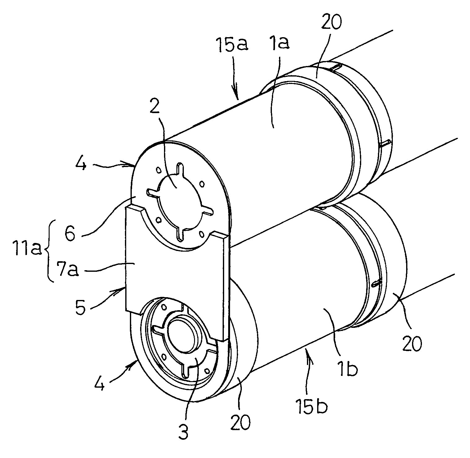
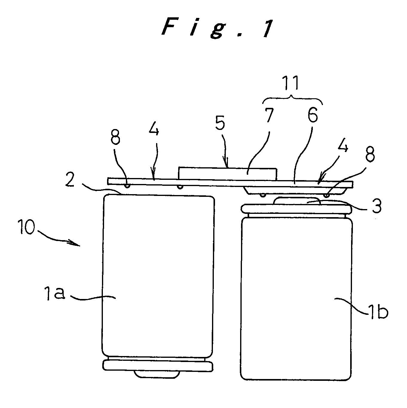
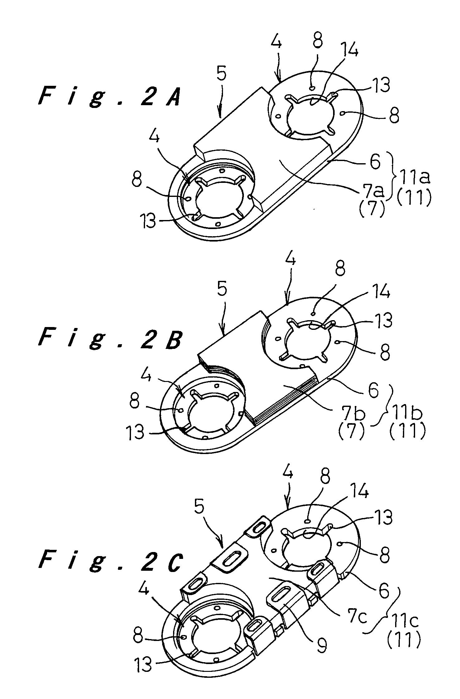
[0034]A first embodiment is first described with reference to FIGS. 1 through 5. FIG. 1 is a front view showing a connection step of a battery pack. A battery pack 10 consists of two batteries 1a, 1b and an inter-batter connection plate 11, as an inter-battery connection device, for connecting between the terminals of the batteries 1a, 1b with different polarities (specifically, between a battery case bottom 2 and a battery sealing plate 3). The inter-battery connection plate 11 is composed of welding portions 4, 4 arranged at its both ends and an intermediate portion 5 connecting the end welding portions 4, 4. The intermediate portion 5 is formed thicker than each welding portion 4. In FIG. 1, the inter-battery connection plate 11 is composed of a base plate 6 including the end welding portions 4, 4 and an intermediate metal plate 7 joined to the base plate 6 at the intermediate portion 5.

[0035]Each end welding portion 4 includes projections 8. The end welding por...

second embodiment

(Second Embodiment)

[0045]A second embodiment is now described with reference to FIGS. 6A through 10. Unlike the first embodiment of the inter-battery connection device, which is composed of a single inter-battery connection plate 11, the inter-battery connection device of the second embodiment is composed of two components, a connection plate 16 and a connection ring 18, joined together. In the following description, the same components as those in the first embodiment are denoted by the same reference numerals and their description will not be repeated.

[0046]As shown in FIGS. 6A to 6C, the inter-battery connection device of the second embodiment includes a connection plate 16 and a connection ring 18. The connection plate 16 includes at one end thereof a thin welding portion 4 for welding to the sealing plate 3 of a battery 1b. The connection plate 16 also includes a thick intermediate portion 5 and a connection arm 17 that has a uniform thickness and extends from its intermediate ...

example

[0052]An inter-battery connection plate lla as shown in FIG. 2A was used to connect batteries 1a, 1b to make a battery pack as one example of the present invention. The inter-battery connection plate 11a was prepared by joining (by any of resistance welding, ultrasonic welding, friction stir welding and laser welding) a 2.6 mm-thick intermediate metal plate 7a made of nickel-plated iron to the middle part of a 0.4 mm-thick base plate 6 made of nickel to form an intermediation portion 5 with a total thickness of 3.0 mm.

[0053]In the connection step using the inter-battery connection plate 11a, two welding electrodes 8 were placed against the projections 8 in the welding portions 4 of the inter-battery connection plate 11a as shown in FIG. 4. One of the welding portions 4 was then welded to the battery case bottom 2 of the one battery la with a diameter of 32 mm while the other welding portion 4 was similarly welded to the sealing plate 3 of the other battery 1b. This completed a batte...


PUM

PropertyMeasurementUnit
thicknessaaaaaaaaaa
diameteraaaaaaaaaa
thicknessaaaaaaaaaa

Abstract

An inter-battery connection device for connecting terminals of two batteries (1a, 1b) arranged with their axes parallel to each other. The inter-battery connection device includes an inter-battery connection plate (11) that connects the battery case bottom (2) and the sealing plate (3) of the two batteries. The inter-battery connection plate (11) includes welding portions (4) at the ends of its base plate (6) for welding to the case bottom (2) and the sealing plate (3), respectively. An intermediate metal plate (7) is joined to the middle part of the base plate (6) between the welding portions (4, 4) to form an intermediate portion (5) having a greater thickness than each welding portion (4). The inter-battery connection device has reduced electric resistance while achieving improved weldability.

Description

TECHNICAL FIELD[0001]The present invention relates to an inter-battery connection device for connecting terminals of batteries arranged in parallel.BACKGROUND ART[0002]In recent years, electronic equipment such as AV devices, personal computers and portable communication devices is rapidly made portable and cordless. For a driving power source of these electronic devices, nickel cadmium storage batteries, nickel metal-hydride storage batteries, lithium secondary batteries and the like have been typically used since they have high reliability and easy maintainability. These batteries are also used in various other applications, particularly increasingly used as driving power sources in power-assisted bicycles, lawn mowers, electric vehicles and other applications where large load characteristics are required. Thus, there is a much need for batteries that have larger current charge / discharge performance suitable for use as driving power sources in these applications.[0003]The battery ...

Claims


Application Information

Patent Timeline
Patent Type & Authority Applications(United States)
IPC IPC(8): C09K21/14H01M50/503H01M50/529H01M50/516H01M50/522
CPCH01M2/202Y02E60/10H01M50/522H01M50/516H01M50/503H01M10/30H01M10/05H01M50/50H01M50/20
Inventor KATO, MASAHIKOFUKUOKA, TAKAHIRO
Owner PANASONIC CORP
Why Eureka
Try Eureka