Three dimensional mapping display system for diagnostic ultrasound machines and method

a three-dimensional mapping and display system technology, applied in the field of diagnostic ultrasound technology, can solve the problems of missing suspicious lesion, difficult to find small tumor in the patient's body, difficult to differentiate from other structures in the same region, etc., to speed up the target finding at subsequent examinations, reduce the time of examination, and eliminate the time-consuming manual labeling of images

Active Publication Date: 2009-05-14
METRITRACK
View PDF33 Cites 64 Cited by
  • Summary
  • Abstract
  • Description
  • Claims
  • Application Information

AI Technical Summary

Benefits of technology

[0014]It is an object of the present invention to significantly reduce the time of the examination by eliminating the time consuming manual labeling of images and speeding up the target finding at subsequent examinations.
[0016]It is a further object of the present invention to enhance correlation capability with other diagnostic imaging modalities like CT scans, MRI, mammograms etc.
[0017]It is yet a further object of the present invention to eliminate or minimize errors due to inaccurate position labeling, therefore reducing the risk of costly lawsuits due to missed diagnosis and decrease the number of callbacks for the patients for repeat examination.
[0018]One advantage, among the many that will be appreciated by those skilled in the arts, is that the present invention provides an easy, uniform, method of communicating the target position among healthcare providers by guiding the ultrasound to a previously recorded target through following the real time display of the ultrasound transducer position in relation to the target coordinates from a previous examination.IV. SUMMARY OF THE INVENTION
[0020]After initial calibration and selection of one or more anatomical reference (nipple, umbilicus etc), positional information associated with each individually recorded image frame or each image in a cine loop is stored with the corresponding image. Using a pointing device with the system display, spatial numerical coordinates of the selected pixel or region, including the distance from the anatomical reference, depth, angle to the body axis and a graphical representation, are displayed next to the ultrasound image. Also displayed are the real time position of the ultrasound probe and target position in a diagram shown next to the real time ultrasound image, providing orientation help for the ultrasound operator.
[0024]This is achieved by continuously monitoring the preset anatomical reference point(s) position, which in the preferred embodiment can be achieved with a magnetic sensor placed next to the anatomical reference on the skin. In an alternate embodiment the anatomical reference tracking can be obtained with an overhead tracking system using digital infrared or optical cameras with or without skin markers. In this embodiment, one camera can be used, or two or more cameras can be also used to achieve a three dimensional stereoscopic effect.

Problems solved by technology

The smaller the tumor is before treatment, the higher the probability of long term patient survival; however, a small tumor is difficult to find in a patient's body and differentiate from other structures in the same region.
Many times a suspicious small finding can coexist in the same region with multiple benign findings (cysts, solid benign nodules, etc), which may create confusion during a follow up exam and may lead to missing the suspicious lesion.
Currently, the automated recording of the transducer position in real time scanning is limited due to the motion of the pre-selected anatomical reference secondary to body and transducer induced motion.
Currently, ultrasound findings are manually labeled by an operator, which is time consuming and prone to errors.
Manual labeling involves the typing of an approximate position in the organ or part of the body, since an accurate position registration is time consuming and, importantly, difficult for the user.
Although multiple ultrasound guidance systems and devices already exist, they do not offer a practical and accurate solution to mapping patient findings in 2D or 3D images in relation to set anatomical reference point(s), which is operator independent during a routine examination, with real time correction for the patient's motion.

Method used


Image

  • Three dimensional mapping display system for diagnostic ultrasound machines and method
  • Three dimensional mapping display system for diagnostic ultrasound machines and method
  • Three dimensional mapping display system for diagnostic ultrasound machines and method

Examples


Embodiment Construction

[0035]Before explaining the preferred embodiment of the present invention in detail, it is to be understood that the present invention is not limited in its application to the details of arrangements of the components set forth in the following description. As will be appreciated by those skilled in the arts, the present invention is capable of other embodiments and of being practiced and carried out in various ways. Also, it is to be understood that the phraseology and terminology employed herein are for the purpose of description and should not be regarded as limiting. It is also to be understood that where ranges are provided for various aspects of the invention and for examples, they are approximate ranges and are not to be limiting except where noted otherwise.

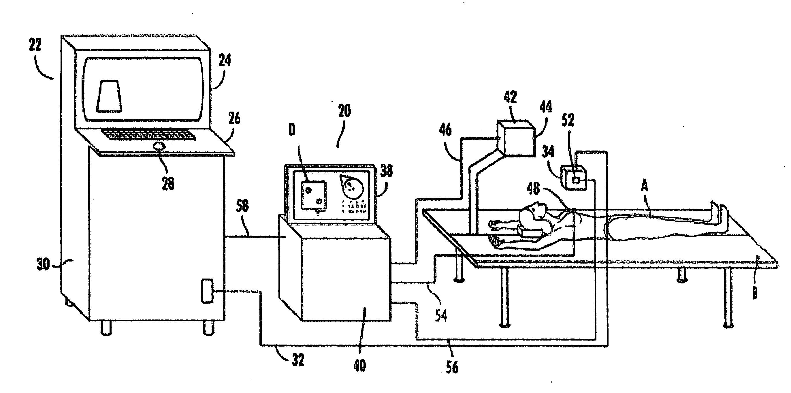
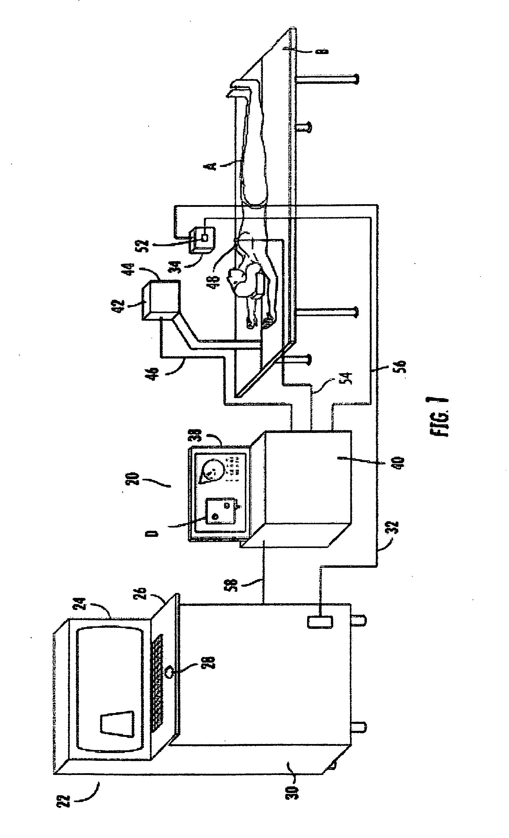
[0036]Turning to FIG. 1, an over view of the physical aspects of an ultrasound device employing the inventive apparatus 20 is seen. Ultrasound machine 22 is a standard device including display 24, interface with keyboard ...


PUM


Abstract

An apparatus, system, and method where the ultrasound transducer position registration is automated, calculates the position of each pixel in the ultrasound image in reference to the predetermined anatomical reference points (AR) and can store the information on demand. The graphic interface associated with the ultrasound image allows for the instant display of selected targets position coordinates relative to anatomical reference points, in the ultrasound images. This system would significantly reduce the ultrasound examination time, by eliminating the time consuming manual labeling of images and speeding up the target finding at subsequent examinations, enhance correlation capability with other diagnostic imaging modalities like CT scans, MRI, mammograms, decrease human errors and fatigue, provide an easy, uniform, method of communicating the target position among healthcare providers.

Description

PRIORITY CLAIM[0001]This application claims the priority of provisional application No. 60 / 999,789 filed Oct. 19, 2007.COMPUTER PROGRAMIncorporation by Reference[0002]This Specification incorporates by reference the material contained on the enclosed compact disc (Appendix A) that includes the source code of the computer program for use with the inventive apparatus. The submission comprises a single compact disc, submitted in duplicate (labeled Copy 1 and Copy 2 and identical in content), created on Oct. 18, 2008 from files created Oct. 14, 2008, entitled Three Dimensional Mapping Display System for Diagnostic Ultrasound Machines and Method and containing the following files:FileSizeCapturePCIBird4.87kbDShowNET81.60kbFileBirdNETApi17.30kbFileBirdNETApiProvider9.68kbMath3D23.30kbMSSQLDBStorageProvider7.74kbMTMDController288.00kbMTMDDatabaseManager71.80kbMTMDFakeVideoCaptureProvider3.44kbMTMDPostgreDBStorageProvider10.90kbMTMDVideoCaptureCardProvider38.90kbMTMDWindowDisplayProvider21....

Claims


Application Information

Patent Timeline
Patent Type & Authority Applications(United States)
IPC IPC(8): A61B8/14
CPCA61B5/06A61B8/00A61B8/4245A61B8/4263G06F19/321G06F19/3406A61B8/483A61B8/4254A61B5/062A61B5/064G16H40/63G16H30/20G16H30/40
Inventor CALUSER, CALIN
Owner METRITRACK
Why Eureka
Try Eureka