
Method and system for reducing errors in vehicle weighing systems

a technology weighing system, which is applied in the field of vehicle weighing system system, can solve the problems that the prior art weighing system was not capable of providing certifiable weights, and achieve the effects of reducing labor intensity, eliminating redundant weighing, and increasing traffic volum

Inactive Publication Date: 2009-05-14
UT BATTELLE LLC
View PDF9 Cites 15 Cited by
  • Summary
  • Abstract
  • Description
  • Claims
  • Application Information

AI Technical Summary

Benefits of technology

[0010]The present invention involves a method and system for vehicle weighing to remove the effects of oscillatory modes due to motion of the vehicle during weighing. It has been discovered that reduction in weighing errors can be made to enable certifiable weight measurements (error ≦0.1%) for a higher traffic volume with less effort (elimination of redundant weighing).
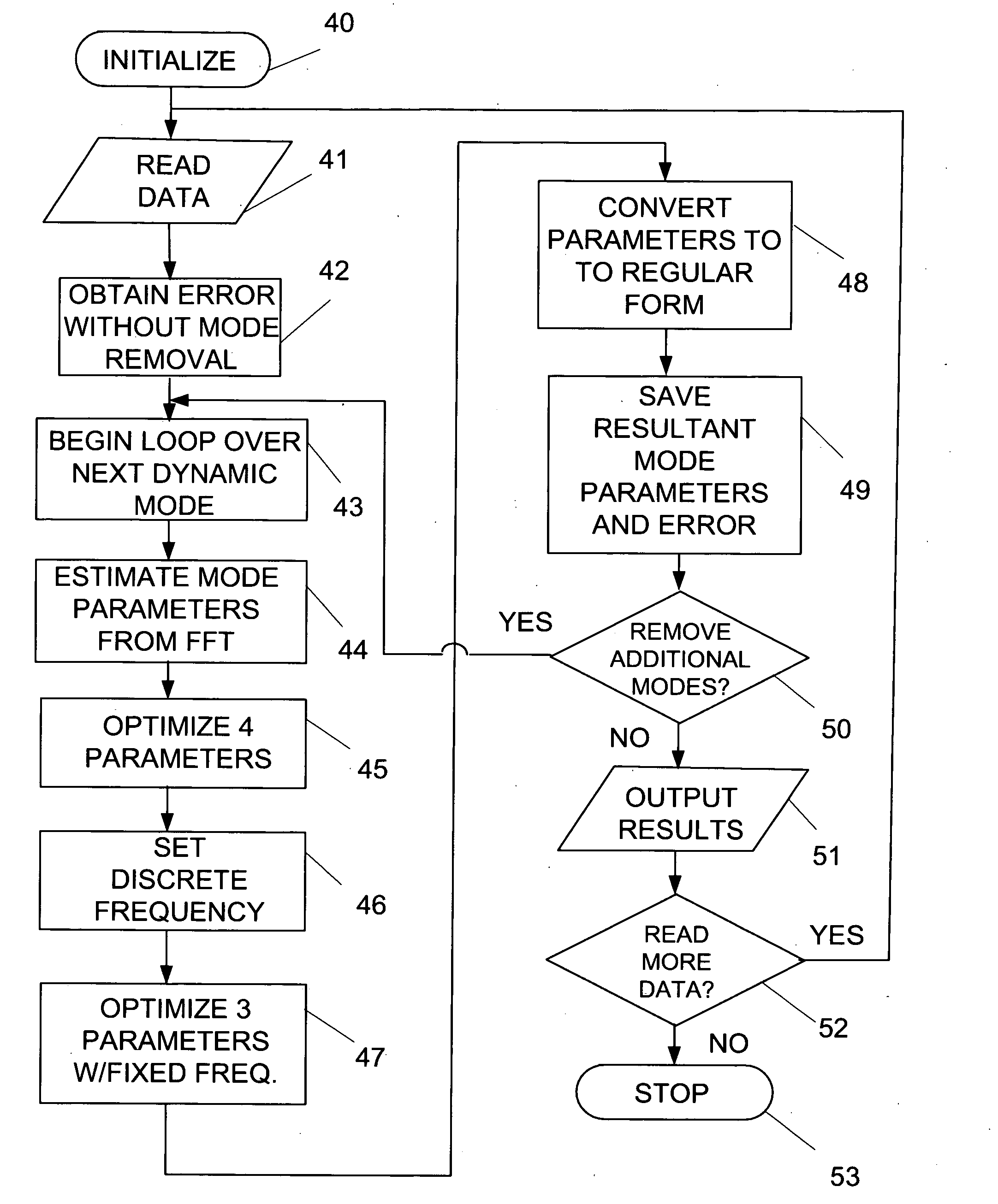
[0011]The method of the present invention involves weighing a vehicle on a plurality of weight-sensing elements and determining vehicle weight with an error of no greater than 0.1%. The method comprises: receiving at least one set of weighing data for a vehicle that has passed over the weight-sensing elements; processing the weighing data to provide a plurality of mode parameters representing oscillatory modes in the data; analyzing the plurality of mode parameters to determine a minimum of error in the weighing data; and removing these dynamical oscillations from the weight data to reduce the error in the weighing data to 0.1% or less.

Problems solved by technology

The weigh-in-motion system of the prior art was not capable of providing certifiable weights, due to natural oscillations, such as vehicle bouncing and rocking and other vehicle dynamics during weighing activities.

Method used


Image

  • Method and system for reducing errors in vehicle weighing systems
  • Method and system for reducing errors in vehicle weighing systems
  • Method and system for reducing errors in vehicle weighing systems

Examples


Embodiment Construction

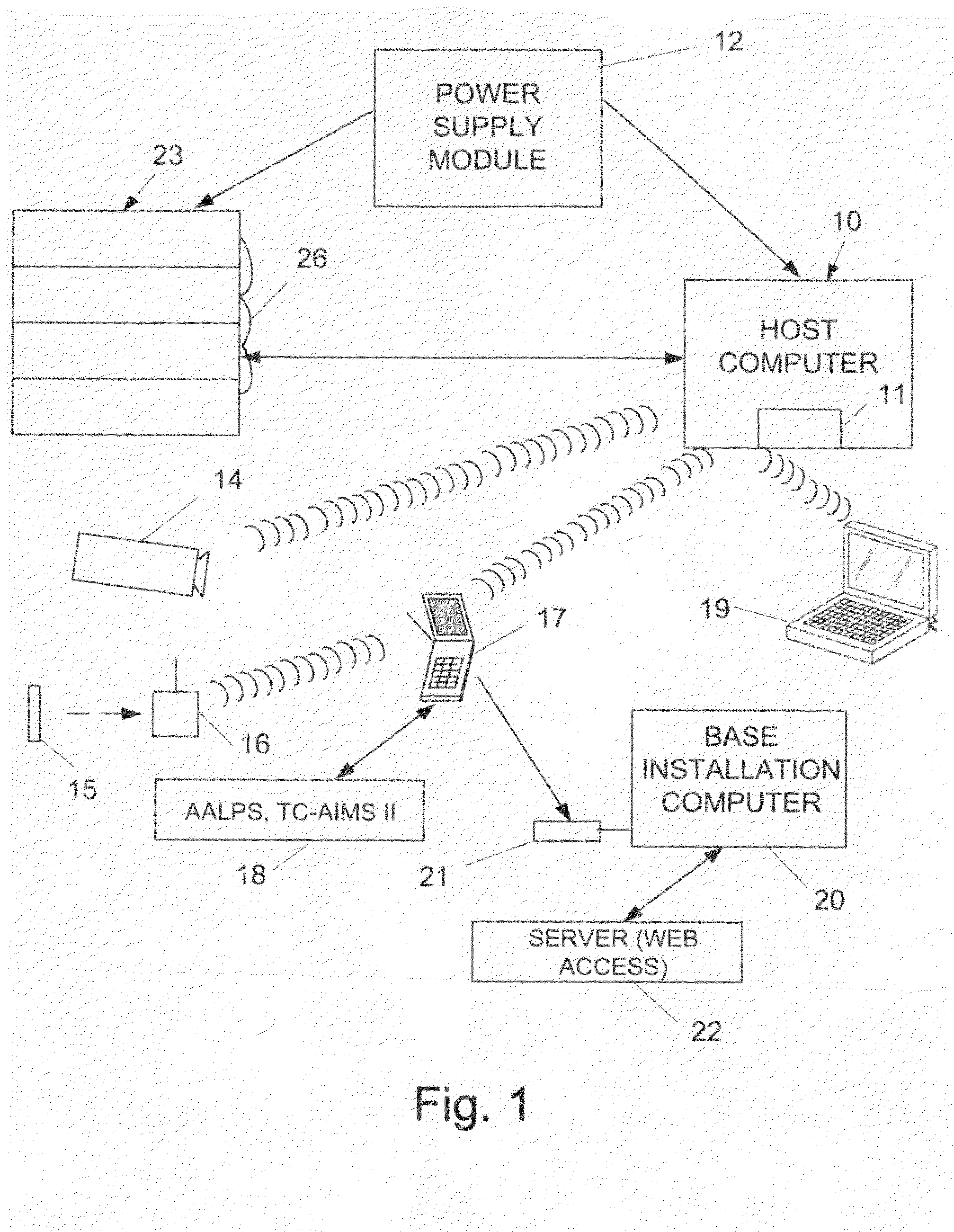
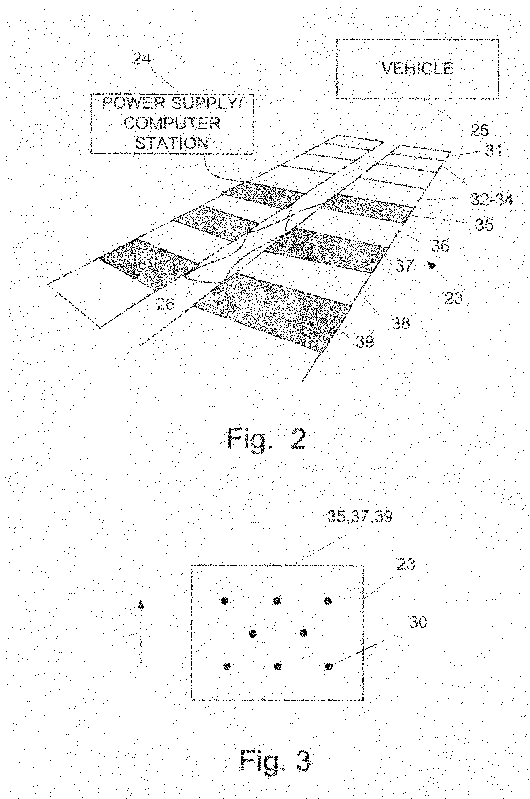
[0024]Referring to FIG. 1, the system of the present invention utilizes a host computer 10 with a network interface 11 according to IEEE Std. 802.11 and a power supply module 12. This network interface 11 can support wireless communication. The host computer 10 and power supply module 11 are connected by cabling to vehicle track elements 23 also referred to herein as weight sensing pads, which are seen in more detail in FIG. 2. The vehicle inspection system also includes a digital camera 14 for imaging a vehicle (FIG. 2) because the system determines both the weight and the volume of the vehicle 25. The vehicle inspection system also includes a bar code reader 16 for reading an identification tag or label 15 on the vehicle. This bar code reader 16 can transmit data wirelessly back to a handheld unit 17, which can further transmit data wirelessly back to the host computer 10. The handheld unit 17 can also be networked to AALPS or TC-AIMS II systems which are described in Beshears et ...


PUM


Abstract

A method and system (10, 23) for determining vehicle weight to a precision of <0.1%, uses a plurality of weight sensing elements (23), a computer (10) for reading in weighing data for a vehicle (25) and produces a dataset representing the total weight of a vehicle via programming (40-53) that is executable by the computer (10) for (a) providing a plurality of mode parameters that characterize each oscillatory mode in the data due to movement of the vehicle during weighing, (b) by determining the oscillatory mode at which there is a minimum error in the weighing data; (c) processing the weighing data to remove that dynamical oscillation from the weighing data; and (d) repeating steps (a)-(c) until the error in the set of weighing data is <0.1% in the vehicle weight.

Description

CROSS-REFERENCE TO RELATED APPLICATIONS[0001]The benefit of priority based on U.S. Prov. App. No. 61 / 003,095 filed Nov. 14, 2007, is claimed herein.STATEMENT REGARDING FEDERALLY SPONSORED RESEARCH[0002]This invention was made with U.S. Government support under Contract No. DE-AC05-00OR22725 awarded to UT-Battelle LLC, by the U.S. Dept. of Energy. The Government has certain rights in the invention.TECHNICAL FIELD[0003]The field of the invention is systems and methods for weighing vehicles, for transport on aircraft and for highway inspections, border security, check points, port entries and for other instances where accurate weights of vehicle and their cargo are needed.BACKGROUND ART[0004]Beshears et al., U.S. Pat. Pub. No. US2006 / 0111868, assigned to the party of interest herein, discloses a system that automatically obtains the following data from a vehicle that is driven slowly (≦5 MPH) over multiple weigh-pads on smooth asphalt or concrete surfaces: weight on each tire; single-a...

Claims


Application Information

Patent Timeline
IPC IPC(8): G01G19/03
CPCG01G19/035G01G23/3735G01G23/06
Inventor HIVELY, LEE M.ABERCROMBIE, ROBERT K.
Owner UT BATTELLE LLC
Learn More