
Process for humidifying synthesis gas

a technology of synthesis gas and process, which is applied in the direction of combustion air/fuel air treatment, gaseous engine fuel, energy input, etc., can solve the problems of insufficient water, insufficient heat generation, and insufficient energy generation above full quench design,

Inactive Publication Date: 2009-05-21
EASTMAN CHEM CO
View PDF7 Cites 9 Cited by
  • Summary
  • Abstract
  • Description
  • Claims
  • Application Information

AI Technical Summary

Benefits of technology

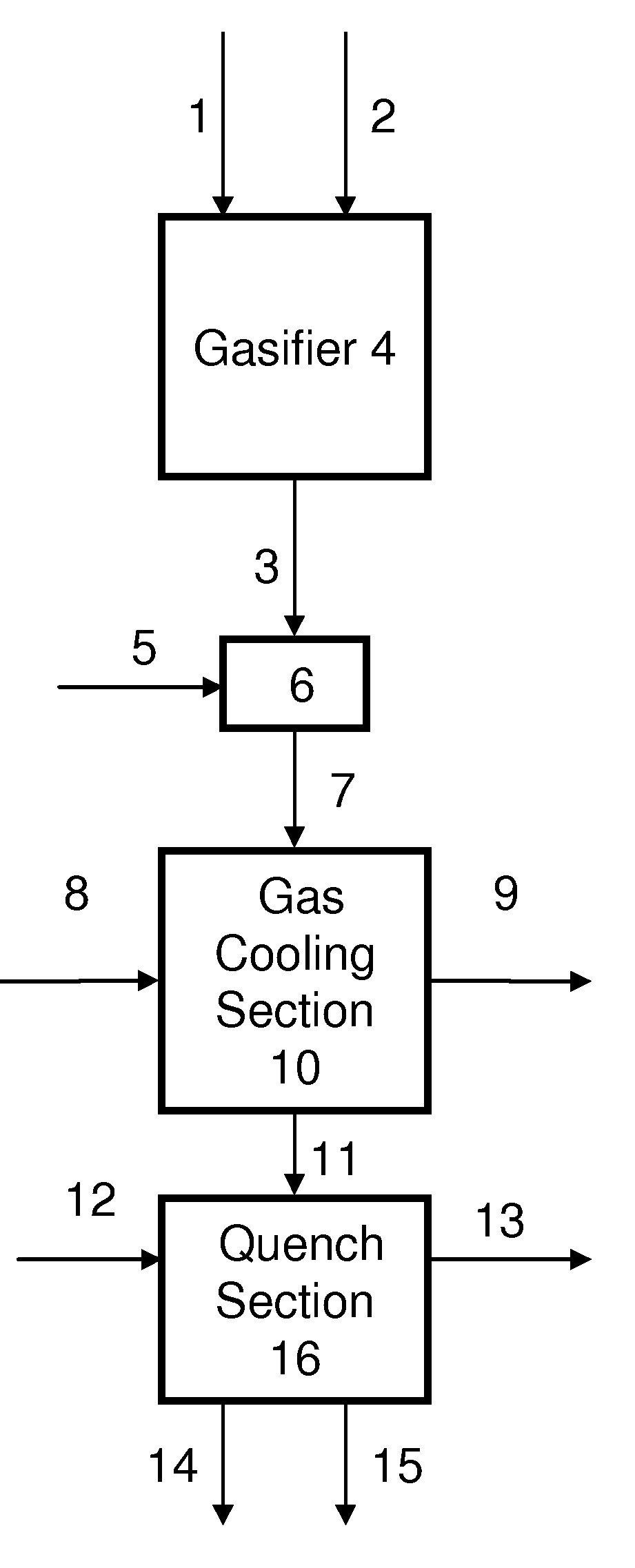
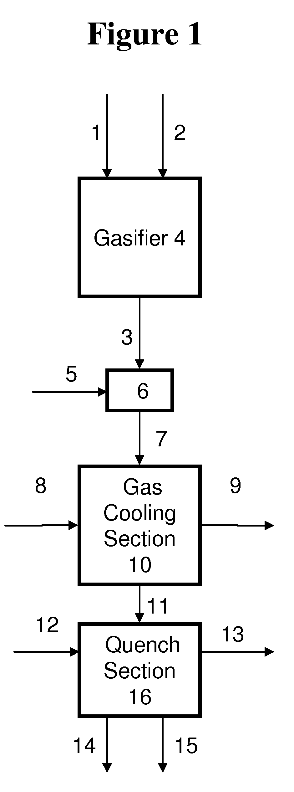
[0015](d) contacting the cooled syngas stream of step (c) with liquid water to produce a humidified syngas stream having a H2O:CO molar ratio of about 0.2:1 to about 4:1.The hot, raw syngas can be combined with a diluent and subjected to cooling heat exchange and quenching operations to retain sufficient sensible heat to vaporize a fraction of the quench water to satisfy a target H2O:CO molar ratio. The H2O:CO molar ratio can be adjusted by varying the flow rate and temperature of a diluent stream mixed with the raw syngas prior to the cooling heat exchange operation. By combining the raw syngas stream with a diluent prior to passing the stream to a heat exchanger, less sensible heat is recovered from the syngas stream and more water is vaporized upon contacting the cooled syngas stream with water. The diluent may comprise a variety of gaseous substances such as, for example, water, steam, recycled syngas, nitrogen, natural gas, methane, ethane, propane, butane, argon, helium, carbon dioxide, waste gases, combustion stack gases, or combinations thereof. The water to carbon monoxide molar ratio also can be controlled by varying the pressure of the steam generated from a portion of the sensible heat of the raw synthesis gas. The process of the invention enables humidification of a syngas stream and the efficient recovery of heat energy that is not used for humidification.
[0039](f) a power producing section comprising a combustion turbine for converting up to 100 volume percent of the a humidified syngas stream from step (a) to electrical power during a period of peak power demand.The system comprises a chemical producing section and a power producing section which can have different syngas requirements during periods of peak and off peak power demands on the power producing section. Accordingly, the amount and / or temperature of the diluent may be selected to produce a syngas having a H2O:CO molar ratio needed for these applications. The amount and / or temperature of the diluent, therefore, can be varied in response to peak and off-peak power demands. As described previously, the chemical producing section can produce one or more chemicals during periods of off-peak power demand. For example, the chemical producing section can produce methanol using a fixed bed or slurry phase methanol reactor. The system may further comprise an acid gas removal section for removing all or a portion of the carbon dioxide, sulfur-containing compounds, or a combination thereof, to reduce poisoning of any process catalysts or to enhance the productivity of the chemical processes. The power producing section may comprise a combustion turbine for converting syngas to electrical power during a period of peak power demand. The power producing section also may further comprise a combined cycle power generating system.

Problems solved by technology

The high price and diminishing supply of natural gas and petroleum has caused the chemical and power industry to seek alternative feedstocks and fuels for the production of chemicals and the generation of electrical power.
In addition, when syngas is used as a fuel for power plants, the presence of water in the syngas is sometimes desirable to retard fouling of the combustion turbine and other equipment.
Often in water slurry-fed gasifiers, there is insufficient water in the cooled syngas effluent from the gasifier to operate a water gas shift reaction at the desired conversion.
Although capable of providing a humidified syngas, the above full quench design is energy inefficient.
Because of the high temperature of the raw syngas, the thermal energy of the raw syngas is degraded to a much lower temperature range and is incapable of generating valuable high pressure steam.
Moreover, the ability to precisely adjust the H2O:CO molar ratio is severely limited.
Gas typically leaves the radiant cooler section at a temperature less than about 800° C. Radiant cooling processes, therefore, enhance the energy efficiency of the gasification process by generating steam from the sensible heat of the raw syngas, but do not address the humidification of the cooled syngas.
The various humidification and cooling methods disclosed in the art do not address the problem of producing a humidified syngas having a broad range of H2O:CO molar ratios that can be varied in response to multiple downstream syngas requirements while, at the same time, efficiently recovering the thermal energy of the syngas stream.

Method used


Image

  • Process for humidifying synthesis gas
  • Process for humidifying synthesis gas

Examples


examples

[0138]General—A better understanding of the invention is provided with particular reference to the examples given below. For Examples 1 through 16, heat and material balance calculations were carried out using process simulation software to illustrate the aspects of the instant invention. The values for temperature, pressure, flow rate, were calculated using standard vapor-liquid equilibrium equations and heat transfer equations known in the art and which may be found in standard engineering texts such as, for example, Perry's Handbook of Chemical Engineering, 6th ed., New York, McGraw Hill, 1984. The following prophetic gas compositions are expected from the indicated gasification conditions: Illinois coal #6 with an expected composition of 61.46 weight % carbon, 12.3% ash, 4.83% sulfur, 12% water, 4.37% hydrogen, 3.87% oxygen, 1.03% nitrogen, and 0.14 weight % chlorine is slurried with water to give an apparent slurry concentration of 64% coal solids. The coal slurry is fed with 0...

examples 1-5

[0147]Examples 1-5 illustrate the effect of varying the diluent flow on the H2O:CO ratio of the humidified syngas when the diluent is water. For examples 1-5, water diluent is combined with the raw syngas and subjected to heat exchange in a gas cooler, and quenched with water to produce a humidified syngas. The gas cooler is designed to remove 7542 BTU / lbmol / hr sensible heat from the syngas at a diluent to raw syngas molar ratio of 0.074:1. The molar ratio of the sum of the quench water flow and water diluent flow to that of the raw syngas is held constant at 2.07:1. The quench water and water diluent temperatures are assumed to be 27° C. less than the calculated quench temperature in all cases. The ratio of molar flow rate of the water diluent to raw syngas is varied from 0:1 to 0.30:1. The results of heat and material balance calculations are summarized in Table 1:

TABLE 1Effect of Diluent Ratio on Humid Gas H2O:CO Molar RatioHumidΔHGCGasKJ / H2O:CODiluentKgmol / TGCinTGCoutMolarTQuenc...

examples 6-8

[0148]Examples 6-8 illustrate the effect of varying the diluent temperature on the H2O:CO ratio of the humidified syngas when the diluent is water. For Examples 6-8, water diluent is combined with the raw syngas and subjected to heat exchange in a gas cooler, and quenched with water to produce a humidified syngas. The molar ratio of the sum of the quench water flow and water diluent flow to that of the raw syngas is held constant at 2.07:1. The temperature of the quench water is assumed to be 27° C. less than the calculated quench temperature in all cases. The results of heat and material balance calculations are summarized in Table 2, with Example 4 for comparison.

TABLE 2Effect of Diluent Temperature on Humid Gas H2O:CO Molar Ratio.Humid GasDiluentTDΔHGCTGCinTGCoutH2O:COTQuenchRatioCelciusKJ / Kgmol / hrCelciusCelciusMolar RatioCelciusExample 40.15:1189.9144561004.2675.72.05212.3Example 60.15:13514188982.3658.31.99211.5Example 70.15:1220144811009.4680.62.06212.5Example 80.17:1351336395...


PUM

PropertyMeasurementUnit
temperatureaaaaaaaaaa

Abstract

Disclosed is a process for humidifying syngas to achieve a water to carbon monoxide molar ratio in the product syngas within a desired range and in which the molar ratio which can be varied over time in response to changes in downstream syngas requirements. The raw syngas is produced by reacting a carbonaceous material with oxygen, water, or carbon dioxide and can be combined with a diluent to produce a diluted syngas stream which can be cooled and contacted with liquid water to give a humidified syngas. The H2O:CO molar ratio of the humidified syngas may be adjusted in response to time-varying downstream syngas requirements by changing the amount and / or temperature of the diluent that is combined with the raw syngas stream, by adjusting quench and heat exchange conditions, or a combination thereof. The application of the process to the coproduction of chemicals and power are also disclosed.

Description

CROSS REFERENCES TO RELATED APPLICATIONS[0001]This application is a divisional application of U.S. application Ser. No. 11 / 311,762, filed Dec. 19, 2005.FIELD OF THE INVENTION[0002]This invention relates to the production of synthesis gas by partial oxidation of carbonaceous materials. More particularly, this invention relates to a process for humidifying synthesis gas produced by the gasification of a carbonaceous material to achieve a water to carbon monoxide molar ratio within a desired range. The H2O:CO molar ratio can be varied over time in response to one or more downstream syngas requirements.BACKGROUND OF THE INVENTION[0003]The high price and diminishing supply of natural gas and petroleum has caused the chemical and power industry to seek alternative feedstocks and fuels for the production of chemicals and the generation of electrical power. By contrast, coal and other carbonaceous fuels such as, for example, petroleum coke, petroleum wastes, biomass, and paper pulping waste...

Claims


Application Information

Patent Timeline
Patent Type & Authority Applications(United States)
IPC IPC(8): C10J3/46
CPCC01B3/34Y02E20/16C01B2203/06C01B2203/061C01B2203/062C01B2203/068C01B2203/0877C01B2203/0883C01B2203/84C10J3/00C10J3/723C10J2300/093C10J2300/0959C10J2300/0969C10J2300/0973C10J2300/1618C10J2300/165C10J2300/1659C10J2300/1665C10J2300/1668C10J2300/1671C10K1/002C10K1/004C10K1/005C10K1/007C10K1/04C10K1/101C10K1/12C10K1/122C10K1/143C10K1/16C10K1/20C10K1/32C10K3/04C10K3/06Y02E20/14Y02E20/18Y02E50/11Y02E50/32C01B2203/0233Y02E50/10Y02E50/30Y02P20/129
Inventor BARNICKI, SCOTT DONALD
Owner EASTMAN CHEM CO
Learn More