
Method for introducing ions into an ion trap and an ion storage apparatus

a technology of ion storage apparatus and ion trap, which is applied in the direction of isotope separation, particle separator tubes, mass spectrometers, etc., can solve the problems of limited viability of approaches, difficult to achieve ejection and detection of both anions and cations stored simultaneously in ion traps in typical ion trap configuration, etc., to reduce the size of the ion cloud and mitigate the effect of coulomb repulsion

Inactive Publication Date: 2009-05-21
SHIMADZU RES LAB EURO
View PDF12 Cites 33 Cited by
  • Summary
  • Abstract
  • Description
  • Claims
  • Application Information

AI Technical Summary

Benefits of technology

[0027]According to the invention there is further provided a method of introducing ions into an ion trap comprising the steps of: using introduction means to introduce first ions into said ion trap through an entrance aperture of the ion trap and adjusting an operating condition of the introduction means, selectively to cause second ions, having opposite polarity to said first ions, to be introduced into the ion trap through the said entrance aperture, whereby said second ions provide charge compensation to mitigate the effects of coulomb repulsion and reduce the size of the ion cloud.

Problems solved by technology

However, until more recently, this aspect of the use of ion traps has been less successful than the utility of the Ion Trap as a Mass Spectrometer (ITMS).
However, the introduction, ejection and detection of both anions and cations stored simultaneously in the ion trap is difficult to achieve in a typical ion trap configuration due to the unipolar nature of the ion optics related to the ion introduction, ejection and detection.
However, this approach has limited viability due to the requirement of using two sets of introduction electrodes, one for analyte ions and the other for reagent ions.
Also, the additional entrance aperture gives rise to undesirable field distortion within the ion trap.
This is a very expensive option and there are currently no commercial available instruments like this.
ECD seems to be very attractive for fragmentation in ion traps and attempts have been made to adapt the technique but, the optimum conditions for ECD can only be achieved using a couple of specific ion trap designs.
However, this technique is still not generally applicable to the most common configurations of ion traps without significant mechanical modifications to the ion trap.

Method used


Image

  • Method for introducing ions into an ion trap and an ion storage apparatus
  • Method for introducing ions into an ion trap and an ion storage apparatus
  • Method for introducing ions into an ion trap and an ion storage apparatus

Examples


Embodiment Construction

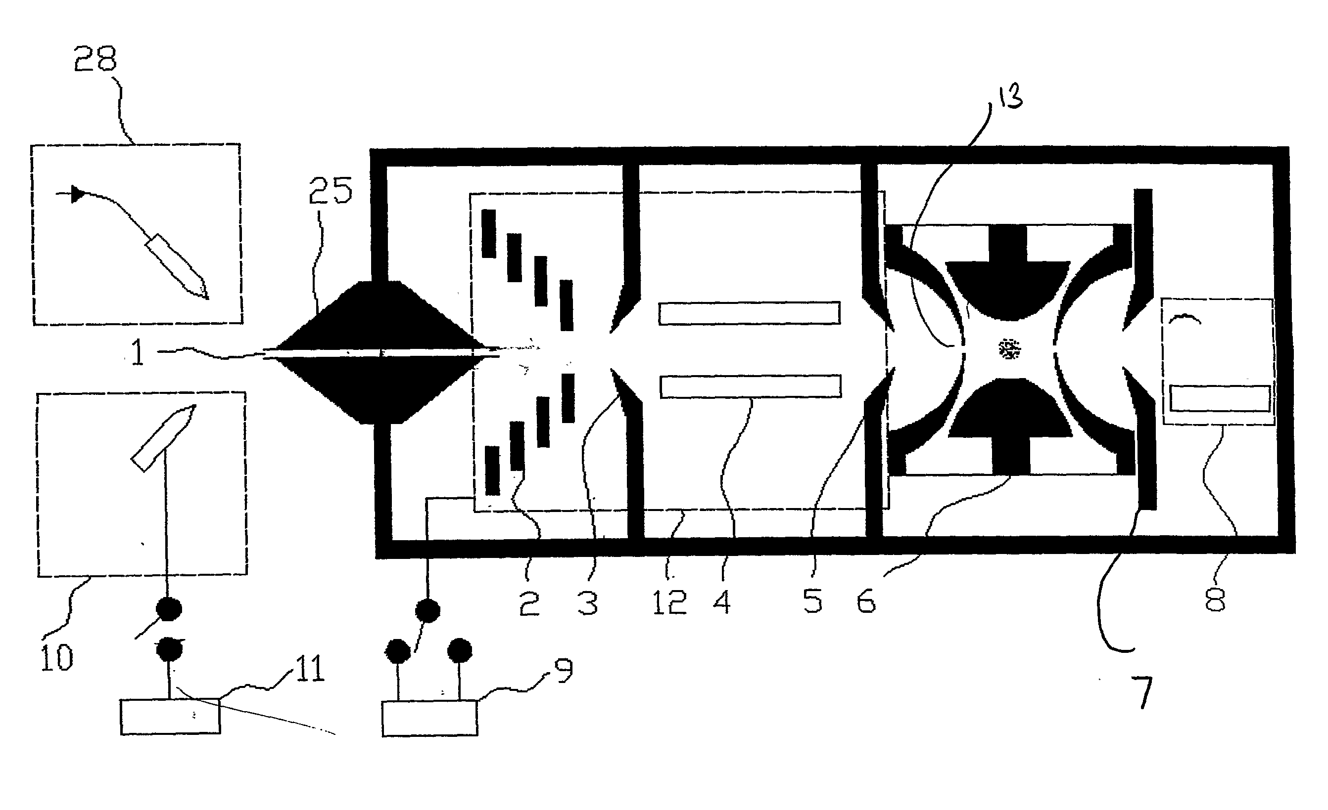
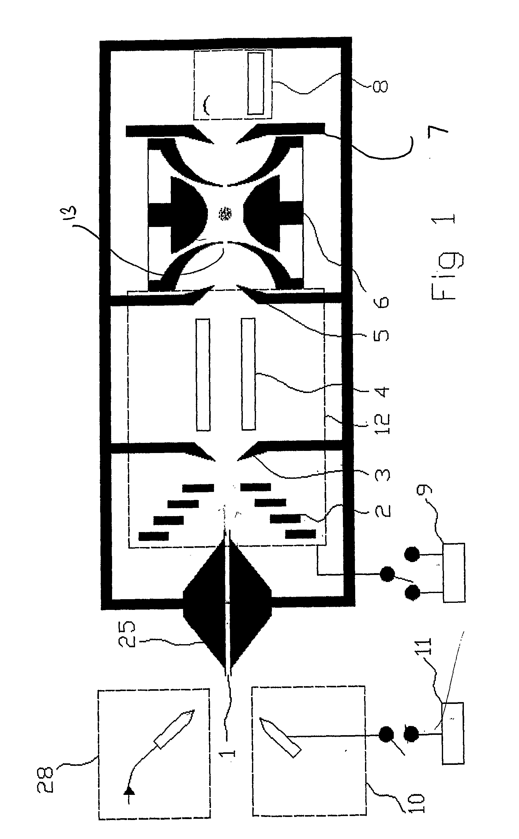
[0039]As illustrated by FIG. 1, the Ion Trap Mass Spectrometer (MS) typically comprises six parts, namely; an analyte ion source 28, a reagent ion source 10, having a controllable power supply 11, an atmospheric pressure / low pressure interface 25, transmission optics 12 having a controllable voltage source 9, an ion trap 6 and a detector 8.

[0040]Electrospray Ionisation (ESI) is one method commonly used to generate singly and multiply charged ions from an organic sample solution. This type of ion source is often used as a link between a Liquid Chromatograph (LC) and a Mass Spectrometer (MS). The atmospheric pressure / low pressure interface 25 is used to pull wet charged particles from the ESI into the vacuum chamber of the MS and dry them, through the so-called desolvation process. The atmospheric pressure / low pressure interface may be in the form of a heated capillary / ion inlet, as illustrated by 1 in FIG. 1, or alternatively a number of cone shaped apertures, between which a heated ...


PUM


Abstract

A method of introducing ions into an ion trap and an ion storage apparatus are described. Introduction means are used to introduce first ions into an ion trap through an entrance aperture to the ion trap. An operating condition of the introduction means is adjusted to cause second ions, of different polarity to the first ions to be introduced into the ion trap through the same entrance aperture.

Description

FIELD OF THE INVENTION[0001]This invention relates to a method of introducing ions into an ion trap and an ion storage apparatus.BACKGROUND OF THE INVENTION[0002]The use of the Quadrupole Ion Trap (QIT) as a means of trapping and storing charged particles was first described in 1953 by W. Paul and H. Steinwedel, Zeitschrift fur Naturforschung, 8A; 1953, p 448 and U.S. Pat. No. 2,939,952. The technology continued to develop, and the QIT was first used as a Mass Spectrometer in 1959, as described in E. Fischer, Zeitschrift f. Physik 156, 1959 p 1-26. Since then, the development of the QIT for ion storage and mass analysis has progressed steadily. This progress is reviewed in “Quadrupole Ion Trap Mass Spectrometry”, Raymond E. March and John F. Todd.[0003]More recently however, attention has been focussed on 2D ion traps, which are also referred to as Linear Ion Traps (LIT) and Digital Ion Traps (DIT) as described in “Ion Motion in the Rectangular Wave Quadrupole Field and Digital Oper...

Claims


Application Information

Patent Timeline
IPC IPC(8): B01D59/44H01J49/00H01J49/04H01J49/06H01J49/16H01J49/42
CPCH01J49/0072H01J49/4295H01J49/062H01J49/0095
Inventor DING, LISMITH, ALAN JOSEPHNIKOLAEVICH, EVGENIJ
Owner SHIMADZU RES LAB EURO
Learn More