Position Sensor for a Downhole Completion Device

a technology of completion device and position sensor, which is applied in the direction of survey, instrument, borehole/well accessories, etc., can solve the problems of limited application value, difficult to ensure the actual position of the moveable element, and limited accuracy of the derived feedback method, so as to facilitate the speed of data transmission

Active Publication Date: 2009-05-21
BAKER HUGHES INC
View PDF15 Cites 50 Cited by
  • Summary
  • Abstract
  • Description
  • Claims
  • Application Information

AI Technical Summary

Benefits of technology

[0013]The position of a movable downhole component such as a sleeve in a choke valve is monitored and determined using an array of sensors, preferably Hall Effect sensors that measure the strength of a magnetic field from a magnet that travels with the sleeve. The sensors measure the field strength and output a voltage related to the strength of the field that is detected. A plurality of se...

Problems solved by technology

Without a positive position indication, it is difficult to ensure the moveable element has actually been moved to the desired position.
Without this feedback, derived feedback methods are used such as that described in U.S. Pat. No. 6,736,213 to try to determine this position, however the derived feedback methods are limited in their accuracy.
Thi...

Method used


Image

  • Position Sensor for a Downhole Completion Device
  • Position Sensor for a Downhole Completion Device
  • Position Sensor for a Downhole Completion Device

Examples


Embodiment Construction

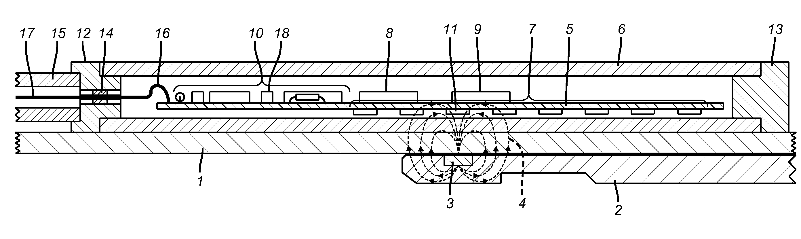
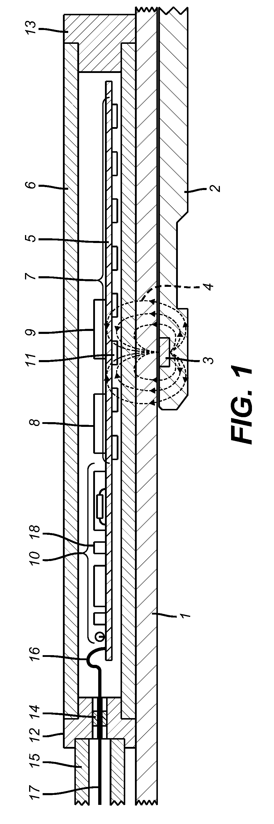
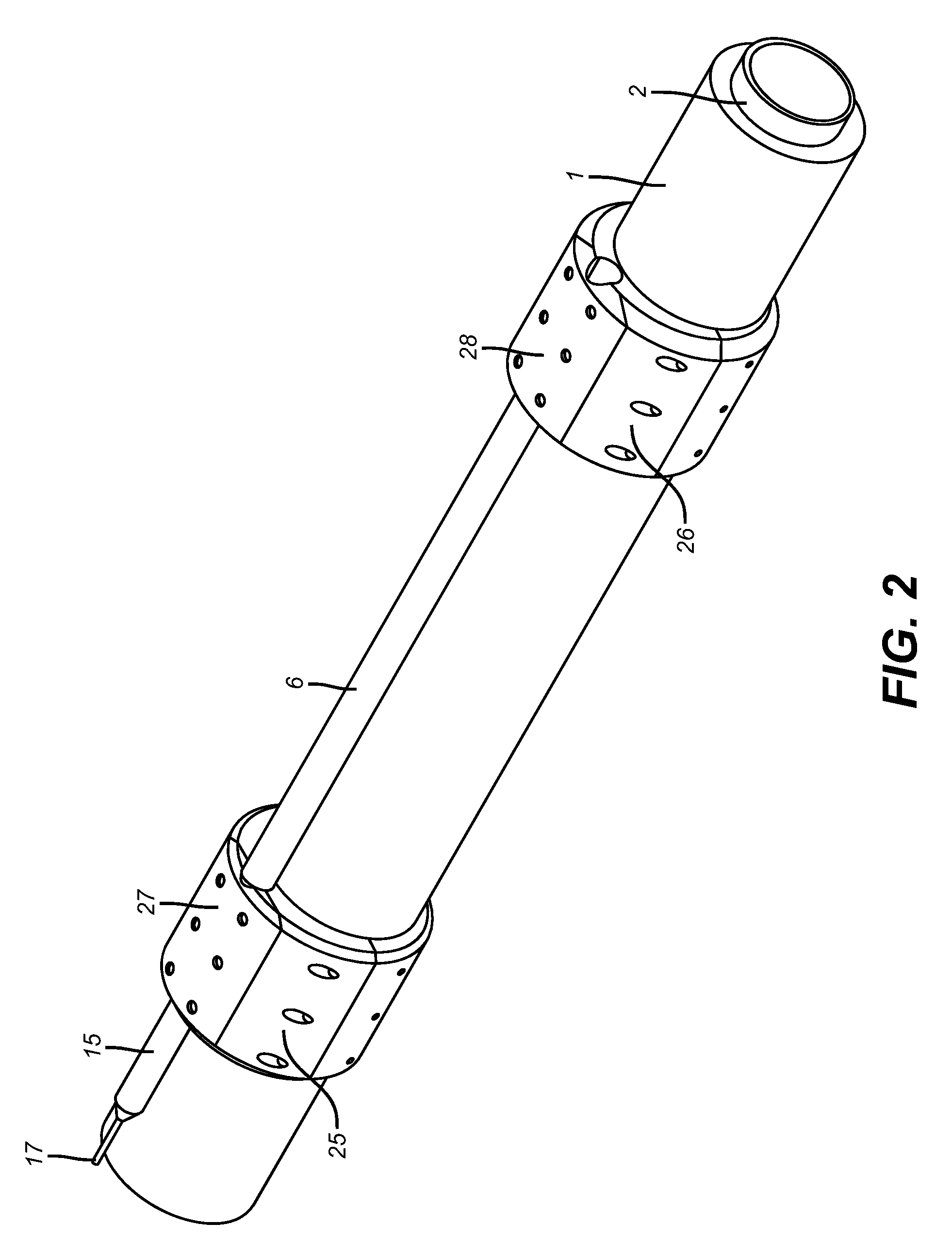
[0029]In one preferred embodiment, the moveable element is part of a remotely actuated sliding sleeve type flow control device. Referring to FIG. 1, tool body 1 is a tubular element attached on the upper end to the production tubing string (not shown) and is thus fixed in place within the well. The lower end contains a series or slots (not shown) arranged around the circumference. Insert 2 is a tubular element enclosed within a tool body 1. The lower end of insert 2 contains a series of slots (not shown) around the circumference arranged to align radially with the slots in tool body 1. A series of seals (not shown) seal off the annular area between the tool body 1 and insert 2 above and below the slots in tool body 1. When an external actuation force is applied to the device, insert 2 moves axially within tool body 1. At one end of the movement range of insert 2, the slots in tool body 1 and insert 2 are aligned allowing flow between the formation and the well. When insert 2 is loca...


PUM


Abstract

The position of a movable downhole component such as a sleeve in a choke valve is monitored and determined using an array of sensors, preferably Hall Effect sensors that measure the strength of a magnetic field from a magnet that travels with the sleeve. The sensors measure the field strength and output a voltage related to the strength of the field that is detected. A plurality of sensors, with readings, transmits signals to a microprocessor to compute the magnet position directly. The sensors are in the tool body and are not mechanically coupled to the sleeve. The longitudinal position of the sleeve is directly computed using less than all available sensors to facilitate the speed of transmission of data and computation of actual position using known mathematical techniques.

Description

PRIORITY INFORMATION[0001]This application claims the benefit of U.S. Provisional Application No. 60 / 988,460, filed on Nov. 16, 2007.FIELD OF THE INVENTION[0002]The field of the invention relates generally to methods for the control of oil and gas production wells. Particularly, it relates to a magnetic position sensing system for determining the position of moveable elements in downhole completion equipment used to control well production and other aspects of well operations.BACKGROUND OF THE INVENTION[0003]In many cases it is desirable to know the position of a moveable element within a downhole tool. This is particularly significant in a downhole flow control device where the position of the moveable element controls the flow into the well. The moveable element in these devices is typically moved by hydraulic or electric means. Without a positive position indication, it is difficult to ensure the moveable element has actually been moved to the desired position. The present invent...

Claims


Application Information

Patent Timeline
IPC IPC(8): G01B7/14
CPCE21B2034/007E21B47/0905Y10T137/0753E21B2200/06E21B47/092E21B47/024E21B47/09E21B34/14
Inventor HOPMANN, DON A.COUSIN, DANIEL M.YERIAZARIAN, LEVON H.FRANCO, JUAN P.JASSER, AHMED J.RANJAN, PRIYESH
Owner BAKER HUGHES INC
Why Eureka
Try Eureka