Antiglare Film

a film and anti-glare technology, applied in the field of anti-glare film, can solve the problems of large number of defects, spaced by a roll pitch, and film appearan

Active Publication Date: 2009-05-21
TOPPAN PRINTING CO LTD
View PDF1 Cites 28 Cited by
  • Summary
  • Abstract
  • Description
  • Claims
  • Application Information

AI Technical Summary

Problems solved by technology

However, the problem is that where defects or foreign matter are present on the emboss roll, the defects spaced by a roll pitch appear on the film.
Therefore, a large number of different types of antiglare films are required according to the application of the display.
Among various display devices, a TN type LCD and VA type LCD often have a problem of an occurrence of a color change and / or a gray scale inversion of an image presented on a display depending on the arrangement of the display device and observer's location.

Method used


Image

  • Antiglare Film
  • Antiglare Film
  • Antiglare Film

Examples


example 1-18

, Comparative Example 1-6

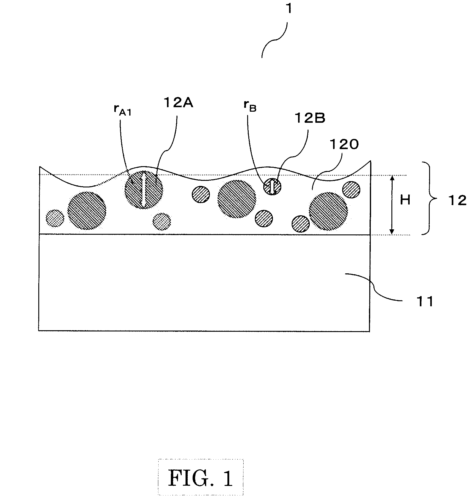
[0096]A triacetyl cellulose film (TD-80U, manufactured by Fuji Photo Film Co., Ltd.) was used as a transparent substrate. The coating liquid for forming an antiglare layer which consisted of a binder matrix forming material, particles A, particles B, and a solvent shown in Table 1 and Table 2 was used as a coating liquid. Although each of materials, refractive indexes, average diameters, and parts by weight of the particles A and the particles B varied, the binder matrix forming material and the solvent were common to all of the Examples 1-18 and Comparative Examples 1-6.

TABLE 1BinderIonizing radiationPentaerythritol triacrylate94.5 pbwRefractivematrixcurable material(by KYOEISHA CHEMICAL)(parts byIndexformingweight)nM:materialPhotopolymerizationIrgacure184 5.0 pbw1.525initiator(by Ciba Specialty Chemicals)AcrylicBYK-350 0.5 pbwadditive(by BYK-Chemie Japan)SolventDioxolan30.0 pbwToluene70.0 pbw

TABLE 2Particles AParticles BRefractiveAveragePart byRefractiveAv...

example 19-36

, Comparative Example 7-12

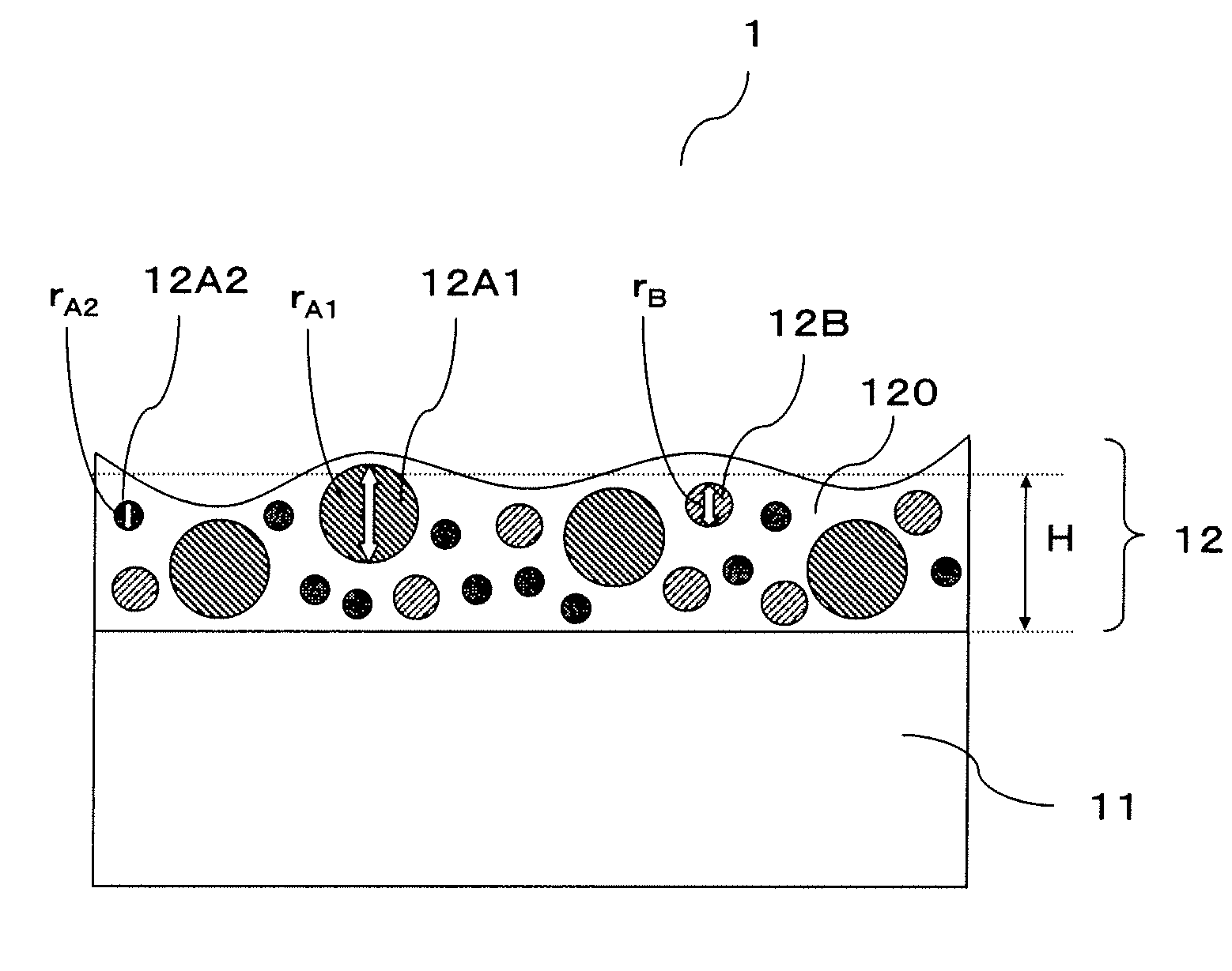
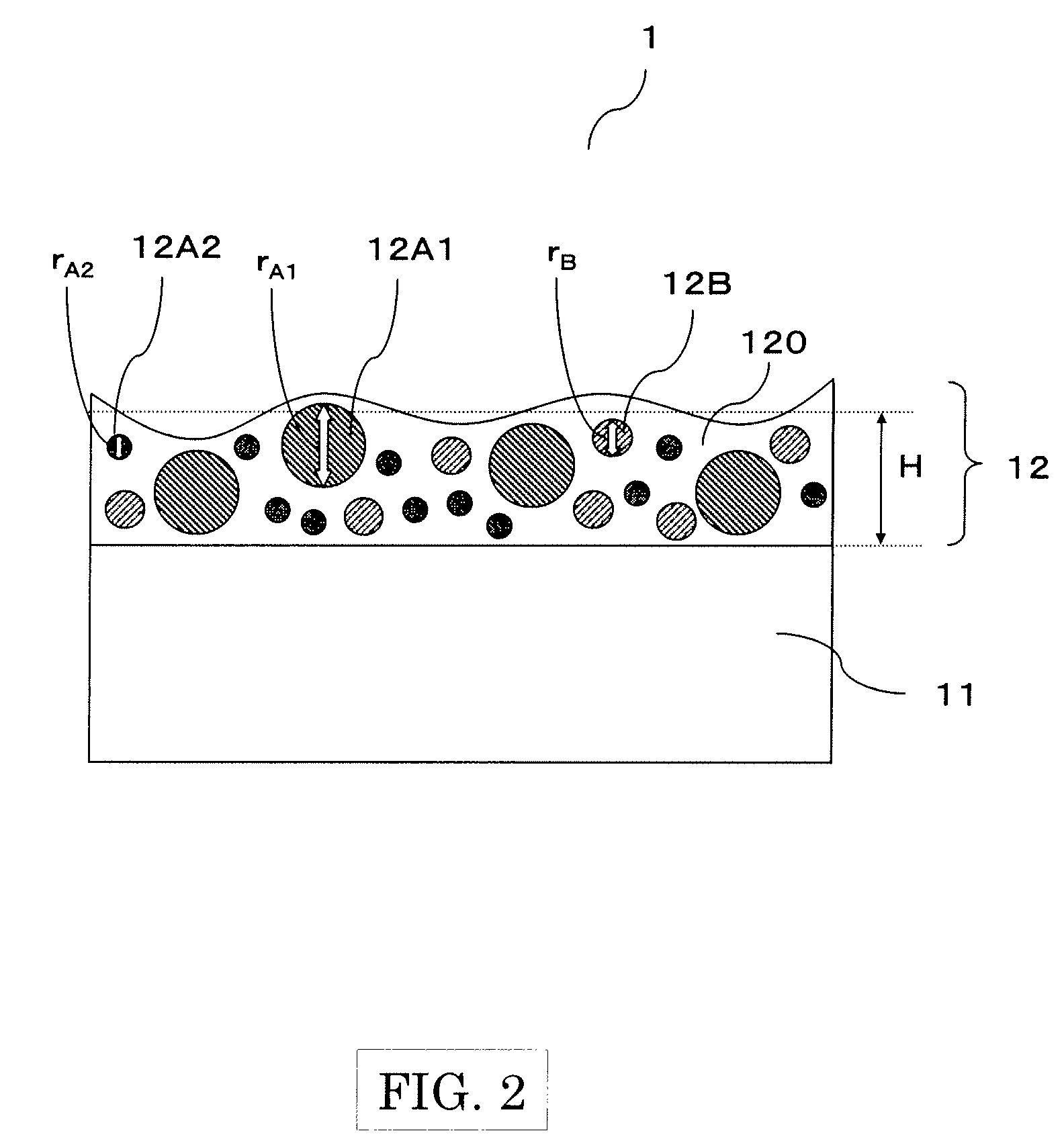
[0100]A triacetyl cellulose film (TD-80U, manufactured by Fuji Photo Film Co., Ltd.) was used as a transparent substrate. The coating liquid for forming an antiglare layer which consisted of a binder matrix forming material, particles A1, particles A2, particles B, and a solvent shown in Table 4 and Table 5A and B was used as a coating liquid. Although each of materials, refractive indexes, average diameters, and parts by weight of the particles A and the particles B varied, the binder matrix forming material and the solvent were common to all of the Examples 19-36 and Comparative Examples 7-12. The particles A1 and A2 were determined in a way that the particle A1 had the larger average diameter.

TABLE 4BinderIonizing radiationPentaerythritol triacrylate94.5 pbwRefractivematrixcurable material(by KYOEISHA CHEMICAL)(parts byIndexformingweight)nM:materialPhotopolymerizationIrgacure184 5.0 pbw1.525initiator(by Ciba Specialty Chemicals)AcrylicBYK-350 0.5 pbwaddi...


PUM

PropertyMeasurementUnit
refractive indexaaaaaaaaaa
viewing angleaaaaaaaaaa
sizeaaaaaaaaaa

Abstract

An embodiment of the present invention is an antiglare film which includes an antiglare layer having particles A, particles B, and a binder matrix on a transparent substrate. A difference in refractive index between the particles A and the binder matrix (|nA−nM|) is 0.060 or less. A difference in refractive index between the particles B and the binder matrix (|nB−nM|) is in the 0.080-0.300 range. An average diameter (unit: μm) of the particles B (rB) is in the 0.5-5.0 μm range. The product value |nB−nM|wBH, which is obtained by multiplying a difference in refractive index between said particles B and said binder matrix (|nB−nM|) by a content (part by weight) of said particles B as against 100 parts by weight of said binder matrix (wB) and an average thickness (unit: μm) of said antiglare layer (H) is in the 10.0-15.0 range.

Description

CROSS REFERENCE TO RELATED APPLICATION[0001]This application is based on and claims the benefit of priority from the Japanese Patent Application number 2007-297751, filed on Nov. 16, 2007; the entire contents of which are incorporated herein by reference.BACKGROUND OF THE INVENTION[0002]1. Field of the Invention[0003]This invention relates to an antiglare film which is preferably applied on a surface of a twisted nematic (TN) type or vertical alignment (VA) type of transmission liquid crystal display (LCD).[0004]2. Description of the Related Art[0005]In the field of displays such as LCD, CRT (Cathode Ray Tube) display, ELD (Electroluminescence Display), and PDP (Plasma Display), providing on the display surface an antiglare film having a concave-convex structure on the surface is known as a means for preventing the degradation of visibility caused by reflection of external light on the display surface during viewing.[0006]The following methods are known for producing such antiglare ...

Claims


Application Information

Patent Timeline
Patent Type & Authority Applications(United States)
IPC IPC(8): G02B1/11
CPCG02B5/0226G02B5/0278G02B5/0242
Inventor YOSHINARI, TOMOTOCHIGI, YUSUKENISHIHARA, TAKASHIHONMA, HIDEAKI
Owner TOPPAN PRINTING CO LTD
Why Eureka
Try Eureka