
Light-enhanced element

a technology of light-enhanced elements and elements, applied in the field of transparent elements, can solve the problems of color spots (such as black or yellow spots), halo phenomena, and brightnesses of conventional leds with inorganic phosphors that are usually not enough for illumination systems, and achieve the effect of increasing the brightness of light-emitting devices or panel display devices

Inactive Publication Date: 2009-05-21
LUMINOSO PHOTOELECTRIC TECH
View PDF10 Cites 25 Cited by
  • Summary
  • Abstract
  • Description
  • Claims
  • Application Information

AI Technical Summary

Benefits of technology

[0006]Accordingly, the objective of the present invention is to provide a light-enhanced element for increasing the brightnesses of the light emitting devices or the panel display devices without changing their original design.
[0010]It is worthy to be noticed that the fluorescent brightening agents used in the present invention can substantially completely absorb the light having a wavelength between 250 nm and 470 nm, and subsequently re-emit it as a visible light with very high luminescence efficiency, and thus only a trace amount of the fluorescent brightening agents are needed for greatly increasing the brightnesses of the light emitting devices or the panel display devices. If the light emitting devices or the panel display devices include the light-enhanced element of the present invention for brightness enhancement, the energy consumption will be saved in average about 10% to 20%. Moreover, the fluorescent brightening agents used in the present invention are environmental-friendly materials, and they will not cause heavy metal pollution and harmful metal radiation problems.

Problems solved by technology

However, the inorganic phosphors can cause the problems phosphors have some limit on brightness enhancement.
For example, the brightnesses of the conventional LEDs with inorganic phosphors are usually not enough for use in illumination systems.
Also, the problems of color spots (such as black or yellow spots) and halo phenomena occurred in the conventional LED exist.
In other applied areas, in the case of panel display devices, the panel display brightness is conventionally increased by increasing the brightness of the light source of the backlight module, and consequently the energy consumption is very high in global view.

Method used


Image

  • Light-enhanced element
  • Light-enhanced element
  • Light-enhanced element

Examples


example 1

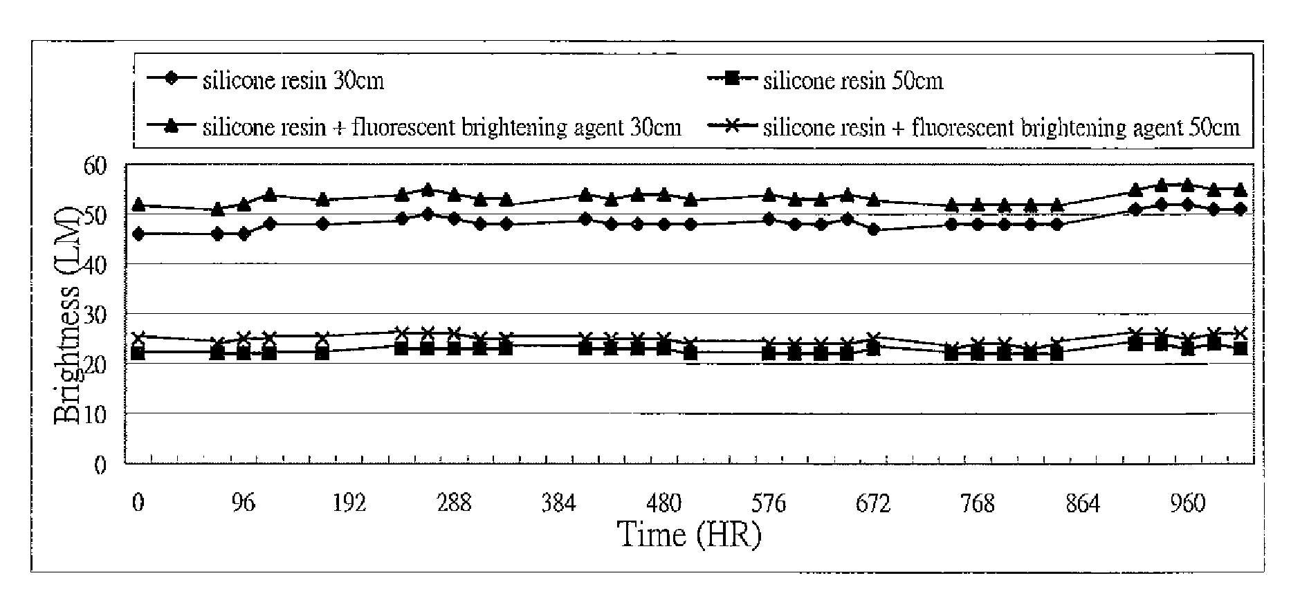
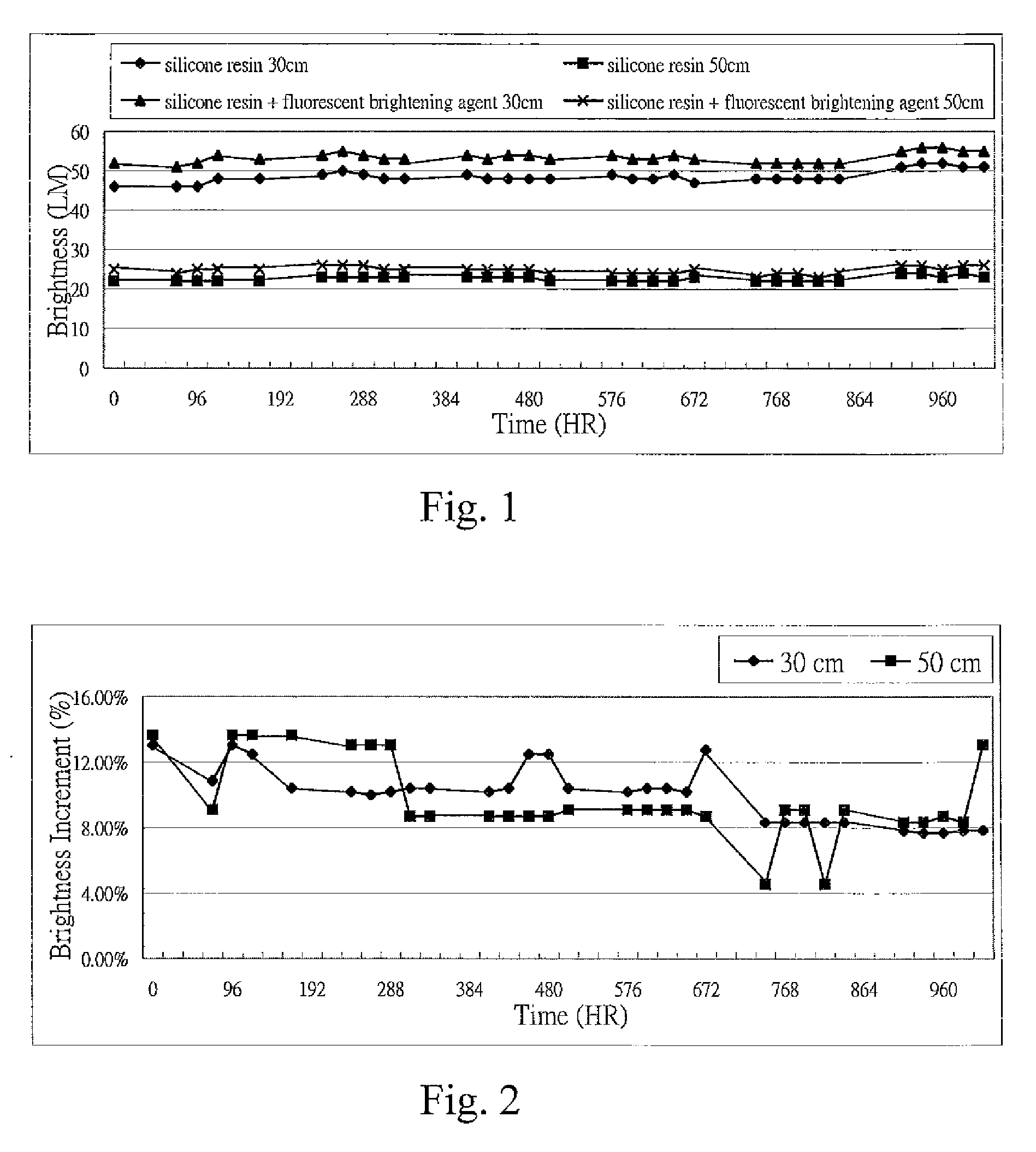
[0064]A GaN LED is die bonded and wire bonded to a PCB. 0.5% by weight of stilbene fluorescent brightening solution is prepared by dissolving stilbene used as a fluorescent brightening agent in acetone. Then, the stilbene-resin mixture is prepared by mechanically mixing 98.0% by weight of silicone resin with 2% by weight of 0.5% stilbene fluorescent brightening solution. Subsequently, the light-enhanced LED device is obtained by encapsulating the GaN LED chip with the fluorescent brightening agent-silicone resin mixture and dried. The stilbene structure is shown as following:

[0065]In addition, a conventional LED device is obtained by encapsulating a GaN LED chip with pure silicone resin and dried.

Brightness Test

[0066]The light-enhanced LED devive, sealed with a transparent encapsulation layer which is made of stilbene-silicone resin mixture, emits a blue light with a wavelength of about 465 nm when subjected to a voltage of 3.6 V, and the blue light emitted outward excites the stilb...

example 2

[0068]The light-enhanced LED device is fabricated by the same method as in EXAMPLE 1 except that benzooxazole is used as a fluorescent brightening agent instead of stilbene. The conventional LED device fabricated in EXAMPLE 1 is used. The benzooxazole structure is shown as following:

Brightness Test

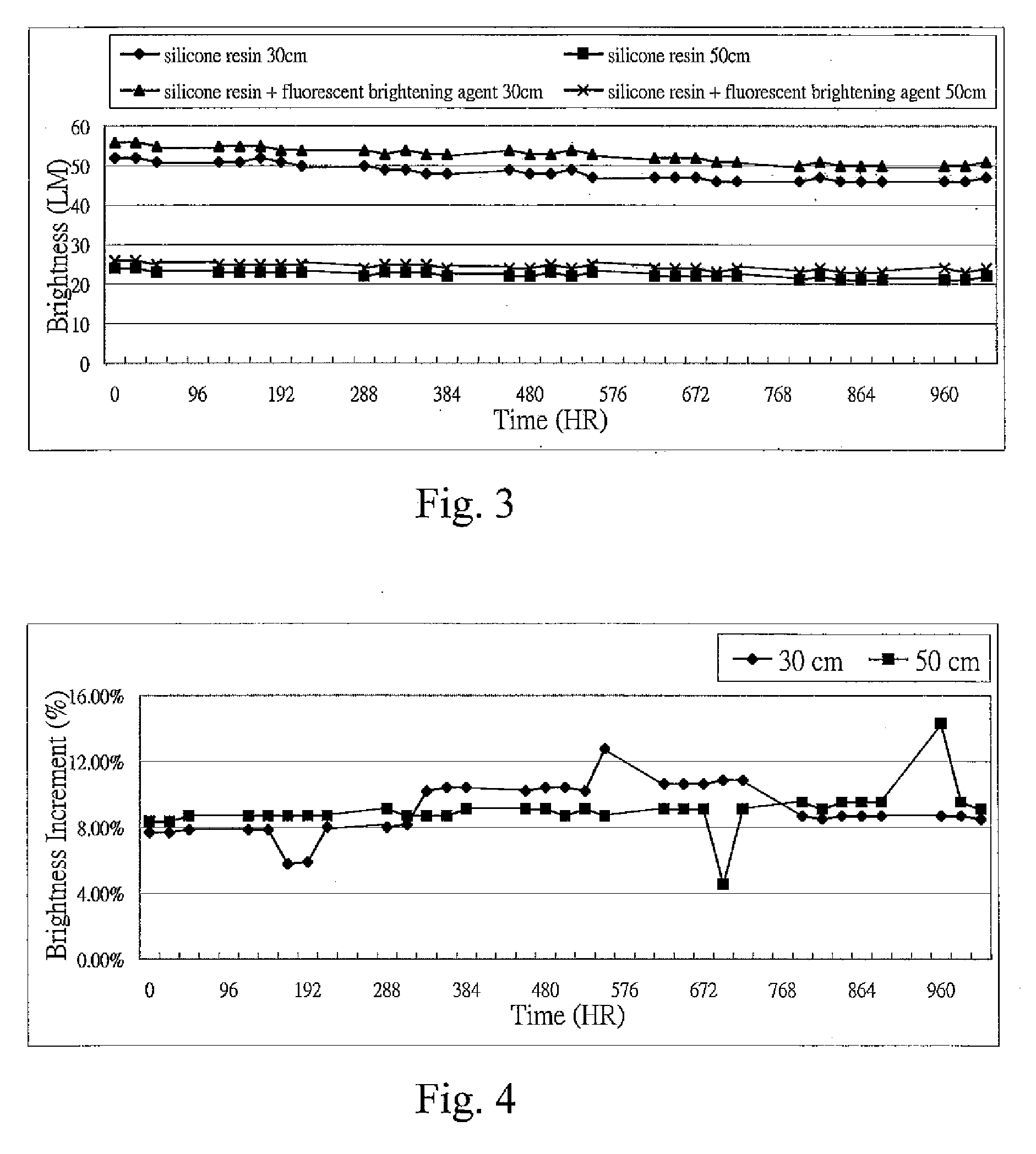
[0069]By using the same method for measuring the brightness as in EXAMPLE 1, the brightness (LM) of the blue light, emitted from GaN LED chip, after passing through a transparent encapsulation layer made of benzooxazole-silicone resin mixture and undergoing wavelength conversion is measured by Illuminance Meter at the height of 30 cm, and 50 cm every 24 hours, respectively, until the total measured time reaches a setting value of 960 hours. The measurement results are shown in FIG. 3. Likewise, the brightness (LM) of the blue light with a wavelength of about 465 nm, emitted from GaN LED chip, after passing through a transparent encapsulation layer made of pure silicone resin is measured by...

example 3

[0071]The light-enhanced LED device is fabricated by the same method as in EXAMPLE 1 except that 9-oxo-xanthene is used as a fluorescent brightening agent instead of stilbene. The conventional LED device fabricated in EXAMPLE 1 is used. The 9-oxo-xanthene structure is shown as following:

Brightness Test

[0072]By using the same method for measuring the brightness as in EXAMPLE 1, the brightness (LM) of the blue light, emitted from GaN LED chip, after passing through a transparent encapsulation layer made of 9-oxo-xanthene-silicone resin mixture and undergoing wavelength conversion is measured by Illuminance Meter at the height of 30 cm, and 50 cm every 24 hours, respectively, until the total measured time reaches a setting value of 960 hours. The measurement results are shown in FIG. 5. Likewise, the brightness (LM) of the blue light with a wavelength of about 465 nm, emitted from GaN LED chip, after passing through a transparent encapsulation layer made of pure silicone resin is measu...


PUM


Abstract

The present invention provides a light-enhanced element including a transparent element including a fluorescent brightening agent, wherein the fluorescent brightening agent can absorb the first light emitted by a light-emitting element and subsequently emits the second light having a wavelength longer than that of the first light.

Description

CROSS REFERENCE[0001]This application is a Continuation-In-Part of U.S. patent application Ser. No. 11 / 475,894, filed Jun. 28, 2006, which is a Continuation-In-Part of U.S. patent application Ser. No. 11 / 330,331, filed Jan. 12, 2005, and for which priority is claimed under 35 U.S.C. § 120, and claims priority to Taiwan Application No. 095109935, filed on Mar. 22, 2006 under 35 U.S.C. § 119, all of which are hereby incorporated herein by reference.BACKGROUND OF THE INVENTION[0002]1. Field of the Invention[0003]The present invention generally relates to a transparent element, and in particular to a light-enhanced element which is a transparent element including a fluorescent brightening agent. The brightness of the light source is greatly increased, when light emitted from the light source passes through such a light-enhanced element.[0004]2. The Prior Arts[0005]The fluorescent materials can be applied in many fields, and are mainly applied in cleaner (such as soaps and detergents), p...

Claims


Application Information

Patent Timeline
IPC IPC(8): C09K11/00
CPCC09K11/06C09K2211/1007C09K2211/1011C09K2211/1029H01L33/502C09K2211/1044C09K2211/1074C09K2211/1088C09K2211/1033
Inventor TSAI, KAI-SHON
Owner LUMINOSO PHOTOELECTRIC TECH
Learn More