Light guide member, planar light source device provided with the light guide member, and display apparatus using the planar light source device

a planar light source and light guide technology, which is applied in the direction of lighting and heating apparatus, instruments, optical elements, etc., can solve the problems of insatiable color reproducibility and response of cold cathode tubes, inability to improve luminance and uniformity, and increase the demand for enlarging liquid crystal displays. , to achieve the effect of reducing the unevenness of colors, reducing the light intensity, and increasing the utilization efficiency of ligh

Inactive Publication Date: 2009-05-21
SHOWA DENKO KK
View PDF5 Cites 45 Cited by
  • Summary
  • Abstract
  • Description
  • Claims
  • Application Information

AI Technical Summary

Benefits of technology

[0043]A light guide member related to the present invention comprises a light reflecting portion formed on the bottom face of the light guide member at a position not near around the luminous device, and a section in which a light reflecting portion is not formed on the bottom face of the light guide member at a position near around the luminous device, in such a manner that the strength of a diffusion upward at the bottom face of the light guide member near around the luminous device is smaller than the strength of a diffusion upward at the bottom face of the light guide member provided with a light reflecting portion at the periphery section thereof. Consequently, a luminance at the section directly over the luminous device is lowered, a luminance distribution on the light emission face of the light guide member can be uniformed, a nonuniformity in luminance and an unevenness of colors can be decreased, a utilization efficiency of a light can be increased, and a high luminance can be implemented.
[0044]By an embodiment of the present invention, there is formed a light semi-permeable portion at a position on the upper face of the light guide member corresponding to the luminous device, or there is formed a light semi-permeable portion having a function for reflecting and diffusing a light on the surface on the concave of the concave for the luminous device formed in the light guide member. Consequently, since a light emitted from the luminous device is diffusely reflected by the light semi-permeable portion, an increase in a luminance at the section directly over the luminous device is suppressed, a luminance distribution on a light emission face of the light guide member can be uniformed, a nonuniformity in luminance and an unevenness of colors can be decreased, a utilization efficiency of a light can be increased, and a high luminance can be implemented.
[0045]Moreover, in the case in which the light guide member is used as a planar light source device, a luminance distribution can be uniformed, a nonuniformity in luminance and an unevenness of colors can be decreased, a utilization efficiency of a light can be increased, a high luminance can be implemented, and the device can be thinned and miniaturized.
[0046]Furthermore, by the planar light source device using such a light guide member, since a luminance at the section directly over the luminous device is lowered, a luminance is uniform, a high luminance can be implemented, an unevenness of colors does not occur, and a chromaticity is uniform for the entire face of the planar light source device.
[0047]Consequently, in the case in which the planar light source device related to the present invention is used as a display apparatus, in particular, a back light for a liquid crystal display, a display apparatus with a thin type and with a high quality image can be obtained.

Problems solved by technology

However, a demand of enlarging a liquid crystal display has been increased in recent years, and such a back light illuminant 100 of the edge light type has a limitation in improving a luminance and a uniformity in the luminance.
In addition, there are problems that color reproducibility and a response of the cold cathode tube is not satisfactory, and that an after-image phenomenon occurs.
However, even in such a case, the above means is insufficient to solve a problem that a luminance at the section directly over the LED lamps 206 becomes higher.
In such a case, a color mixture is insufficient and an unevenness of colors may be found in some cases.
However, this method causes a thickness of a back light to be enlarged, and is not preferable for a flat panel display.

Method used


Image

  • Light guide member, planar light source device provided with the light guide member, and display apparatus using the planar light source device
  • Light guide member, planar light source device provided with the light guide member, and display apparatus using the planar light source device
  • Light guide member, planar light source device provided with the light guide member, and display apparatus using the planar light source device

Examples


embodiments

Embodiment 1

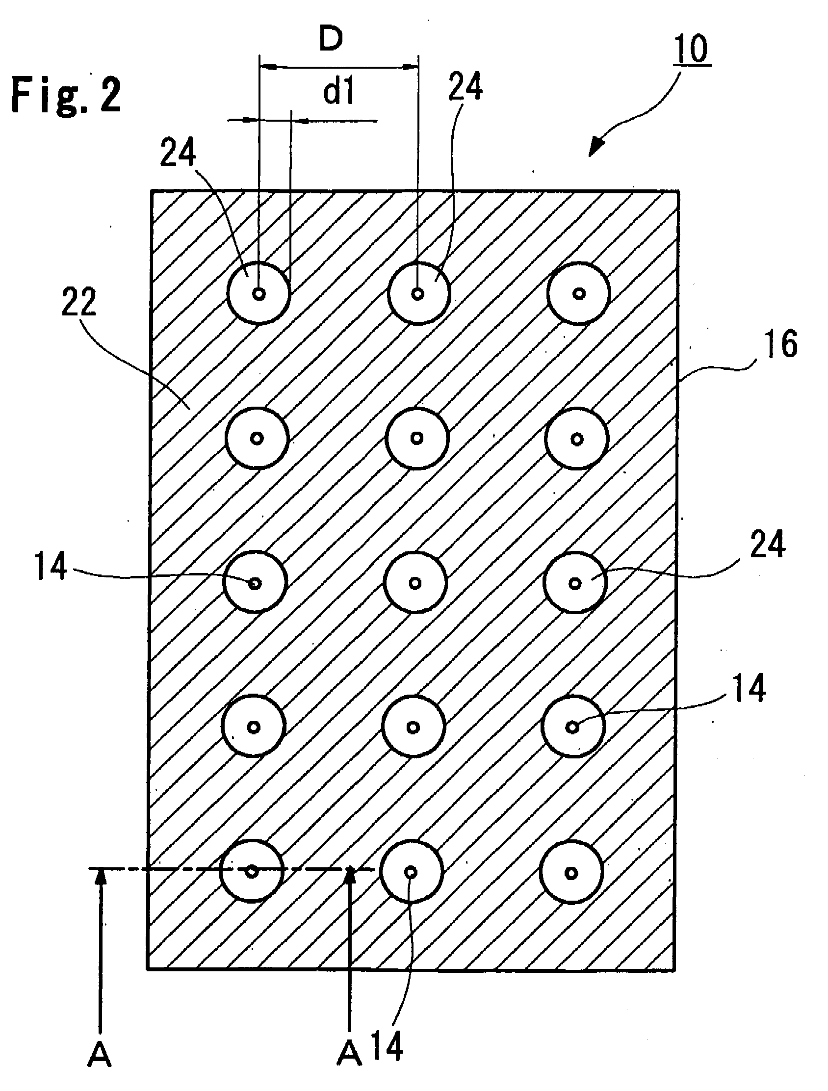
[0194]The unit luminous devices in which LED chips of red, green, and blue of a 1 W class are combined as the luminous device 14 were disposed in an array pattern, as shown in FIG. 2, on the luminous device mounting substrate 12 of transverse 115 mm×longitudinal 135 mm.

[0195]A transparent plate made of an acrylic resin of transverse 115 mm×longitudinal 135 mm and a thickness of 3 mm was prepared as the light guide member 16.

[0196]A concave for luminous device 20 in a semi-spherical shape with a radius of 2.5 mm was formed on the bottom face 18 of the light guide member 16 at the position directly over the center of each luminous device 14.

[0197]A white paint made of an acrylic resin containing titanium dioxide of 50% (only a solid matter) was coated on the bottom face 18 of the light guide member 16 by a spray coating in such a manner that a film thickness is 100 μm, thereby forming the light reflecting portion 22.

[0198]In this case, the light reflecting portion 22 was f...

embodiment 2

[0204]A planar light source device 10 related to the present invention as shown in FIG. 19 was obtained similarly to Embodiment 1 except for the following points.

[0205]More specifically, as shown in FIGS. 8 and 9, a light semi-permeable portion 32 in a circular shape is further formed at the position on the upper face of the light guide member 16 corresponding to the luminous device 14, that is, at the position directly over the luminous device 14.

[0206]A white paint made of an acrylic resin containing titanium dioxide of 50% (only a solid matter) was coated on the upper face area of the light guide member, in which a distance d2 from the luminous device 14 to a peripheral edge of the light semi-permeable portion 32 is 5 mm, by a spray coating in such a manner that a film thickness is 20 μm, thereby forming the light semi-permeable portion 32.

[0207]By this, a relative luminance was then measured at a distance of 0.5 mm from the position O on the upper face of the diffusing plate dir...

embodiment 3

[0209]A planar light source device 10 related to the present invention as shown in FIG. 20 was obtained similarly to Embodiment 1 except for the following points.

[0210]More specifically, a light semi-permeable portion 11 is formed on the surface on the concave of the concave for luminous device 20.

[0211]A white paint made of an acrylic resin containing titanium dioxide of 50% was coated by a spray coating in such a manner that a film thickness is 20 μm, thereby forming the light semi-permeable portion 11.

[0212]A range in which the light semi-permeable portion 11 is formed, that is, a projection distance d3 from the center of the luminous device 14 to a peripheral edge of the light semi-permeable portion 11 is approximately 1.8 mm in such a manner that the LED chips of red, green, and blue are almost covered as shown in FIG. 20.

[0213]A white paint made of an acrylic resin containing titanium dioxide of 50% was coated on the almost entire face of the bottom face 18 of the light guide ...


PUM

PropertyMeasurementUnit
thicknessaaaaaaaaaa
thicknessaaaaaaaaaa
thicknessaaaaaaaaaa

Abstract

A light guide member laminated on the upper face of a luminous device mounting substrate on which a luminous device is mounted and which is for diffusing and guiding upward light emitted from the luminous device. The light guide member includes a light reflecting portion formed on the bottom face of the light guide member in an area other than an area near the luminous device, and a section in which a light reflecting portion is not formed on the bottom face of the light guide member at a position near the luminous device. Also disclosed is a planar light source device provided with the light guide member, and a display apparatus using the planar light source device.

Description

CROSS REFERENCES TO RELATED APPLICATIONS[0001]This application is an application filed under 35 U.S.C. §111(a) claiming benefit pursuant to 35 U.S.C. §119(e) (1) of the filing date of Provisional Application 60 / 748,191 filed on Dec. 8, 2005 and 60 / 789,128 filed on Apr. 5, 2006 pursuant to 35 U.S.C. §111(b).TECHNICAL FIELD[0002]The present invention relates to a light guide member, a planar light source device, and a display apparatus using the planar light source device. In detail, the present invention relates to a light guide member, a planar light source device provided with the light guide member, that are used as an illuminant such as an advertising lamp, an illumination, and a back light for a liquid crystal display, and that are capable of uniformly diffusing and guiding upward a light from a luminous device, and a display apparatus using the planar light source device such as a liquid crystal display apparatus.BACKGROUND ART[0003]In recent years, there is widely used a displ...

Claims


Application Information

Patent Timeline
Patent Type & Authority Applications(United States)
IPC IPC(8): G02F1/13357G02F1/1335H01L33/60
CPCG02B6/0021G02B6/0055H01L33/60G02F1/133603G02F1/133611G02B6/0068G02F1/133605
Inventor TOKITA, KOJIWATANABE, TAKEONAIJO, SHUICHIGOMI, SHUJI
Owner SHOWA DENKO KK
Why Eureka
Try Eureka