Image processing system, mask fabrication method, and program

Active Publication Date: 2009-05-21
MOFIRIA
View PDF4 Cites 38 Cited by
  • Summary
  • Abstract
  • Description
  • Claims
  • Application Information

AI Technical Summary

Benefits of technology

[0022]According to the present invention, an image processing system, a mask preparation m

Problems solved by technology

At this time, portions unnecessary for the authentication, for example, the system, background, etc. similarly end up standing

Method used


Image

  • Image processing system, mask fabrication method, and program
  • Image processing system, mask fabrication method, and program
  • Image processing system, mask fabrication method, and program

Examples


Example

First Embodiment

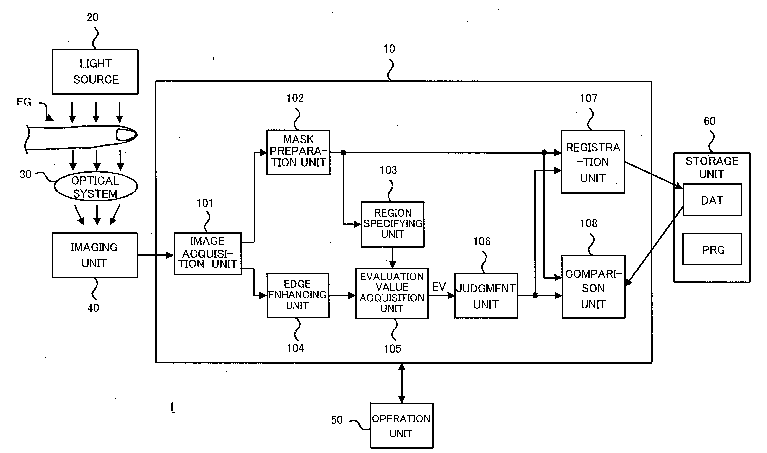
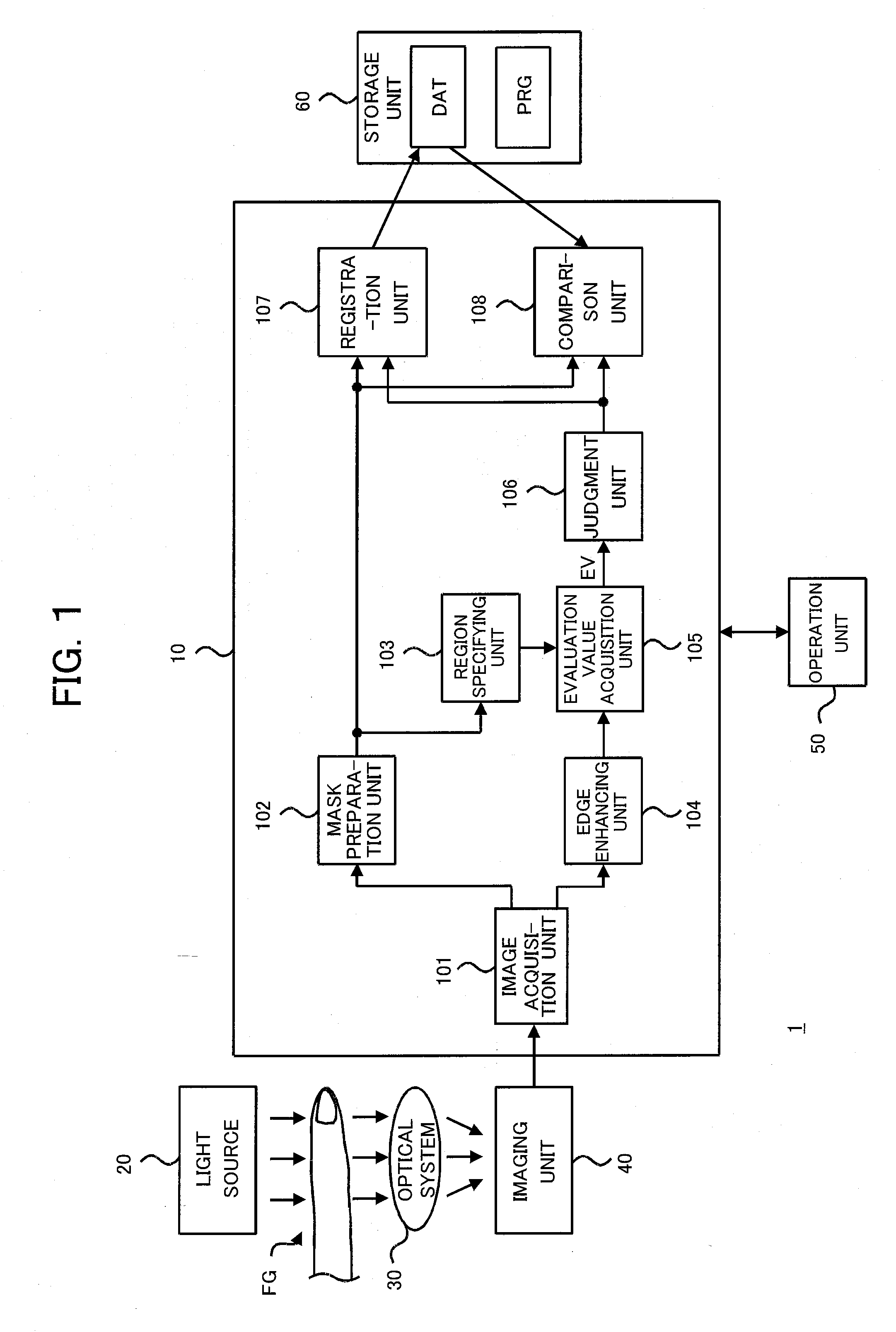
[0052]FIG. 1 is a diagram showing an example of the configuration of an image processing system 1 according to an embodiment of the present invention.

[0053]The image processing system 1 has a control unit 10, light source 20, optical system 30, imaging unit 40, operation unit 50, and storage unit 60.

[0054]The light source 20 generates light striking an object FG, for example, in the example of FIG. 1, the finger of a person. This light is near-infrared light having a wavelength of for example about 600 nm to 1300 nm and has the properties of relatively high transmission through human tissue and distinctive absorption by the hemoglobin in the blood. The light source 20 is configured by for example a light emitting diode, a halogen lamp, etc.

[0055]The optical system 30 guides the light transmitted through the object FG to a light receiving surface of the imaging unit 40. In the image of the object FG projected onto the light receiving surface of the imaging unit 40, th...

Example

[0241]A second embodiment of the present invention will be explained next.

[0242]In the image processing system according to the second embodiment of the present invention, the positions of the border lines of the object are estimated based on the distribution of edge pixels.

[0243]FIG. 22 is a diagram showing an example of the configuration of a mask preparation unit 102A in the image processing system according to the present embodiment. The mask preparation unit 102A has an edge extraction unit 211, border line acquisition unit 212, pixel extraction unit 213, division unit 214, approximation line acquisition unit 215, pixel extraction unit 216, border line acquisition units 217 and 218, and mask generation unit 219.

[0244]The edge extraction unit 211 is an embodiment of the edge extraction unit and the edge extracting means of the present invention.

[0245]The border line acquisition unit 212 is an embodiment of the second border line acquisition unit and the second border line acquir...


PUM


Abstract

An image processing system and a mask preparation method able to prepare a mask by simple processing and a program executed in such an image processing system are provided. To extract the edges of the image, strings of pixels corresponding to the contours of an object are extracted from the edge extracted image, and border lines for the masking are acquired based on an approximation line thereof.

Description

TECHNICAL FIELD[0001]The present invention relates to an image processing system for preparing a mask used when cutting out an image of a predetermined object from an image and a mask preparation method and program for the same.[0002]The present invention for example relates to an image processing system for preparing a mask used when cutting out an image of a biometric feature from an image captured for biometric authentication.BACKGROUND ART[0003]Along with the advances made in information communications utilizing networks, a personal authentication system having a higher safety is demanded.[0004]Biometric authentication judges whether or not a person is a true registered person based on information obtained from physical characteristics of the person, for example, a fingerprint, voice print, retinal pattern, and vein pattern of a finger, therefore has the excellent characteristic that another person assuming the identity of a true person can be much reduced.[0005]Japanese Patent ...

Claims


Application Information

Patent Timeline
IPC IPC(8): G06K9/00G06K9/40G06K9/48G06V10/26G06V10/46G06V40/12G06V40/14
CPCG06K9/00006G06K2009/00932G06T7/0083G06T2207/10048G06K9/48G06T2207/30196G06K9/00G06K9/34G06T2207/30101G06T7/12G06V40/12G06V40/14G06V10/26G06V10/46G06T7/00G06T3/00G06T1/00G06F18/00
Inventor ABE, HIROSHI
Owner MOFIRIA
Why Eureka
Try Eureka