Spindle Apparatus

a spindle and apparatus technology, applied in the direction of auxillary equipment, electrical-based machining electrodes, manufacturing tools, etc., can solve the problems of unstable electrical contact between the base side and the spindle, increased axial vibration of the spindle, and difficult rotation of the spindle about its axis with high precision, etc., to achieve high precision

Active Publication Date: 2009-05-28
SODICK CO LTD
View PDF8 Cites 11 Cited by
  • Summary
  • Abstract
  • Description
  • Claims
  • Application Information

AI Technical Summary

Benefits of technology

[0006]The first connection means preferably makes electrical connection between the base side and the second spindle reliable, and is, for example, a brush (15, 36) pressed against the second spindle.
[0007]The second connection means is, for example, a flexible electrical wire (17, 39) or a helical spring (51). Even if axial vibration arises in the second spindle due to the first connection means, the second connection means has a degree of mechanical freedom, which means that there is the ef

Problems solved by technology

With a spindle apparatus in which a brush is pressed against the spindle, rotating the spindle about its axis with high precision is difficult.
However, a higher pressing force increases axial vibration o

Method used


Image

  • Spindle Apparatus
  • Spindle Apparatus
  • Spindle Apparatus

Examples


first embodiment

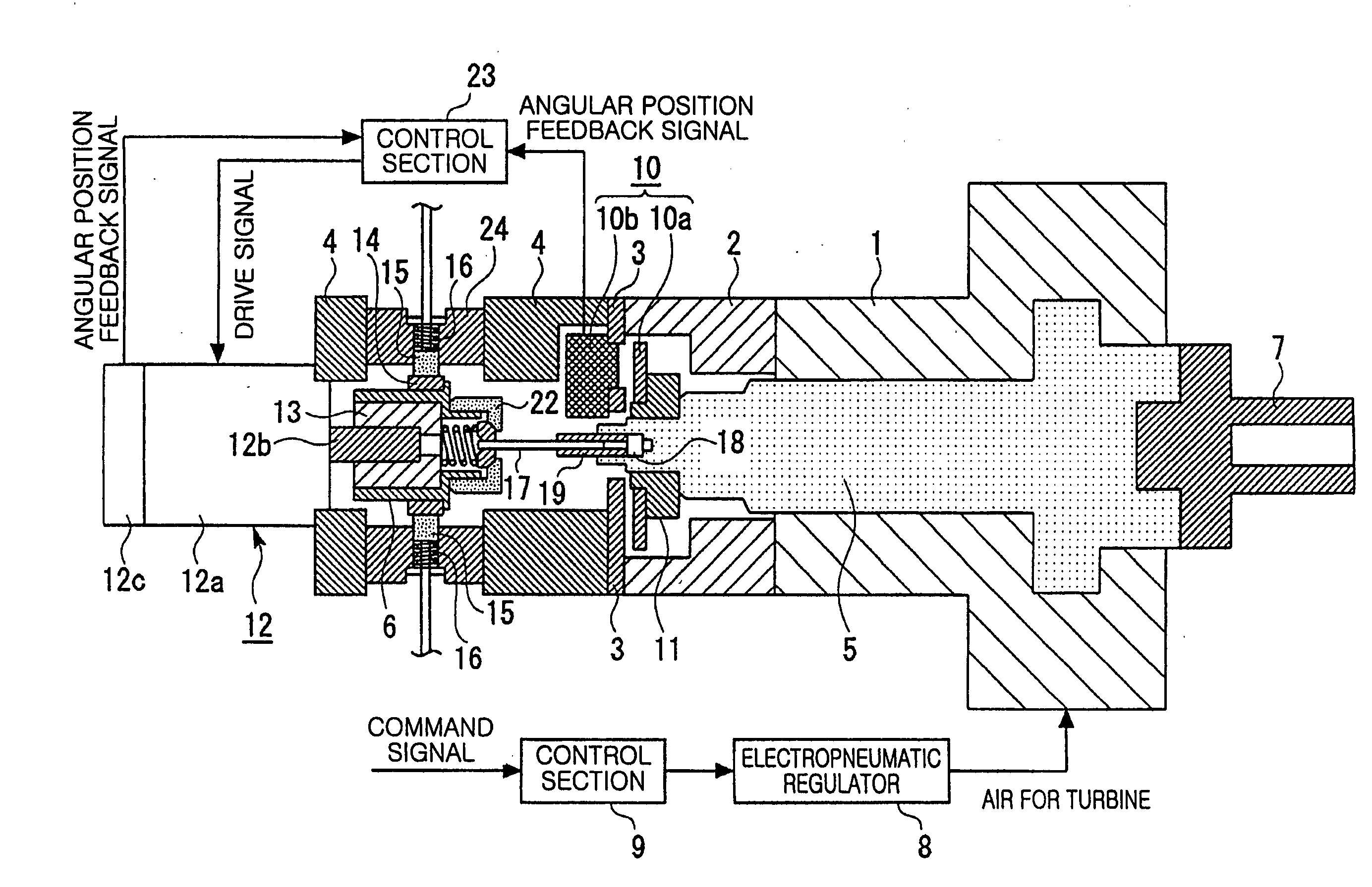
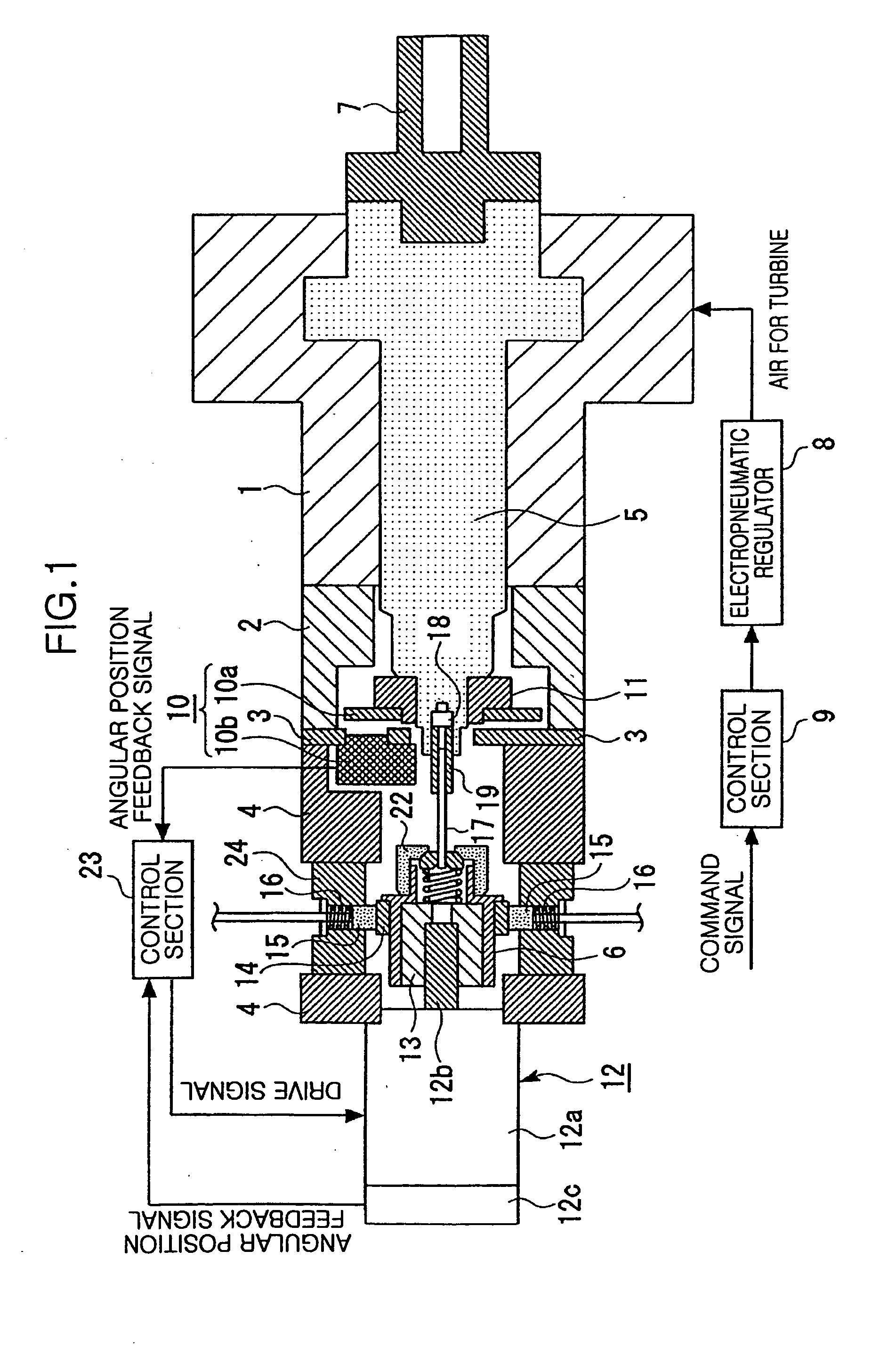
[0014]a spindle apparatus will now be described with reference to FIG. 1 and FIG. 2.

[0015]As shown in FIG. 1, the spindle apparatus of the present invention is provided with a bearing housing 1, a cylindrical connecting member 2, a disc-shaped detection head attachment plate 3, and a cylindrical motor retention member 4. These components integrally form a base. The spindle apparatus of FIG. 1 is also provided with first and second spindles 5, 6 made of a conductive material. The first spindle 5 is supported by an air hydrostatic bearing (not illustrated) built into the bearing housing 1, enabling rotation of the spindle with extremely high accuracy about an axis extending in the lateral direction in FIG. 1. A desired tool can be attached to the tip end of the first spindle 5 using a tool holder 7. The desired tool is, for example, an electrode used for electric discharge machining. A turbine blade (not shown) is provided on the first spindle 5, which is a turbine rotor that is rotat...

second embodiment

[0018]a spindle apparatus will now be described with reference to FIG. 3.

[0019]The spindle apparatus shown in FIG. 3 is provided with a housing 31 forming a base, and first and second spindles 32, 33 housed in the housing 31. The first and second spindles 32, 33 are formed from a conductive material. The first spindle 32 is supported by an air hydrostatic bearing 30 built into the housing 31, thereby enabling rotation with extremely high accuracy about an axis extending in the vertical direction in FIG. 3. A desired tool can be attached to the lower end of the first spindle 32 using a tool holder (not shown). The first spindle 32 is rotated by a coreless motor 34. The coreless motor 34 is formed from a permanent magnet section 34a, constituting a rotor, and a coil section 34b constituting a stator. The permanent magnet section 34a is fixed to the first spindle 32 and the coil section 34b is fixed to the housing 31. A rotary encoder 35 consisting of a rotation plate 35a and a detecti...

third embodiment

[0022]a spindle apparatus will now be described with reference to FIG. 4. The same reference numerals as are used in FIG. 3 denote the same elements in FIG. 4, and detailed description of those elements is omitted.

[0023]Differing from the second embodiment, the third embodiment does not use flexible electrical wire 39. Instead, a helical spring 51 is provided as second connecting means for electrically connecting the first spindle 32 and the second spindle 33. The helical spring 51 is arranged so that its axis is in alignment with the axes of the spindles 32 and 33. The helical spring 51 can be fixed to the spindles 32 and 33 using the same methods as used for the electrical wire 17. The helical spring 51 has a degree of mechanical freedom, which means that compared to the case where the connection between the spindles 32 and 33 is performed using a rigid body, a force that would be transmitted from the second spindle 33 to the first spindle 32 to cause axial vibration in the first ...


PUM

PropertyMeasurementUnit
Forceaaaaaaaaaa
Flexibilityaaaaaaaaaa
Electrical conductoraaaaaaaaaa

Abstract

A spindle apparatus includes a rotatable first spindle (5, 32) to which a tool can be attached. The first spindle is supported in a base with high precision using an air hydrostatic bearing. The spindle apparatus further includes a second spindle (6, 33) capable of rotation about an axis substantially aligned with the axis of the first spindle, first connection means for electrically connecting a base side and the second spindle, and second connection means for electrically connecting the first spindle and the second spindle. Electrical connection between the base side and the first spindle is carried out via the first and second connection means. The first connection means is, for example, a brush (15, 36). The second connection means has a degree of mechanical freedom and is, for example, a flexible electrical wire (17, 39) or a helical spring (51).

Description

FIELD OF THE INVENTION[0001]The present invention relates to a spindle apparatus used in a machine tool such as an electric discharge machine or a machining center.BACKGROUND ART[0002]A spindle apparatus includes a base, such as a housing, and a spindle supported so as to be capable of rotation with respect to the base. A tool is fitted to the spindle, either directly or via a tool holder. A spindle apparatus having electrical contact between the base and the spindle in order to supply electrical current from the base side to the spindle and lead sensor signals from the spindle to the base side is known. Sensor signals may be signals indicating contact between a tool and a workpiece. Japanese patent No. 3238218 and Japanese examined patent application No. 3-058851 disclose a spindle apparatus in which electrical current for electric discharge machining is supplied to a tool via the spindle. In Japanese patent No. 3238218, a conducting ring is provided on the spindle, and a brush is ...

Claims


Application Information

Patent Timeline
IPC IPC(8): B23B19/02
CPCB23H7/26B23H7/265B23H7/28B23H2400/10Y10T82/2562Y10T82/2561Y10T82/266Y10T82/2552B23Q1/0009
Inventor ARAIE, ICHIROKAWADA, SHUICHIHASEGAWA, TARO
Owner SODICK CO LTD
Why Eureka
Try Eureka