Laser ignition system

a laser ignition and laser technology, applied in the direction of engine ignition, combustion engines, machines/engines, etc., can solve the problems of increasing the size of the apparatus and the increase in the cost, the difficulty of mounting a conventional laser ignition system on an engine room of recent vehicles that are substantially highly integrated, and the limitation of the flame formed by a conventional ignition plug from spreading

Inactive Publication Date: 2009-05-28
DENSO CORP +1
View PDF5 Cites 18 Cited by
  • Summary
  • Abstract
  • Description
  • Claims
  • Application Information

AI Technical Summary

Benefits of technology

[0013]To achieve the objective of the present invention, there is provided a laser ignition system, which includes a laser oscillator and an oscillation controller. The laser oscillator is configured to generate laser light into a combustion chamber of an engine. The oscillation controller is configured to cause the laser oscillator to generate a plurality of laser pulses into the combustion chamber in order to ignite the engine. The oscillation controller causes the laser oscillator to generate each of the plurality of laser pulses at a laser oscillation period that is longer than 10 μs and shorter than 300 μs.

Problems solved by technology

In general, flame formed by a conventional ignition plug is limited from spreading in the above lean air-fuel mixture.
The method of JP-A-2002-295256 requires high energy of 35 mJ as shown in FIG. 2 of JP-A-2002-295256, and thereby the increase in size of the apparatus and the increase in cost may be caused.
However, in order to charge the laser generation source with substantial energy for generating the laser light at the above short pulse intervals, substantially large electric current is required to be fed to a single laser generation source.
Therefore, the conventional laser ignition system may be difficult to be mounted on an engine room of recent vehicles that are substantially highly integrated.

Method used


Image

  • Laser ignition system
  • Laser ignition system
  • Laser ignition system

Examples


Embodiment Construction

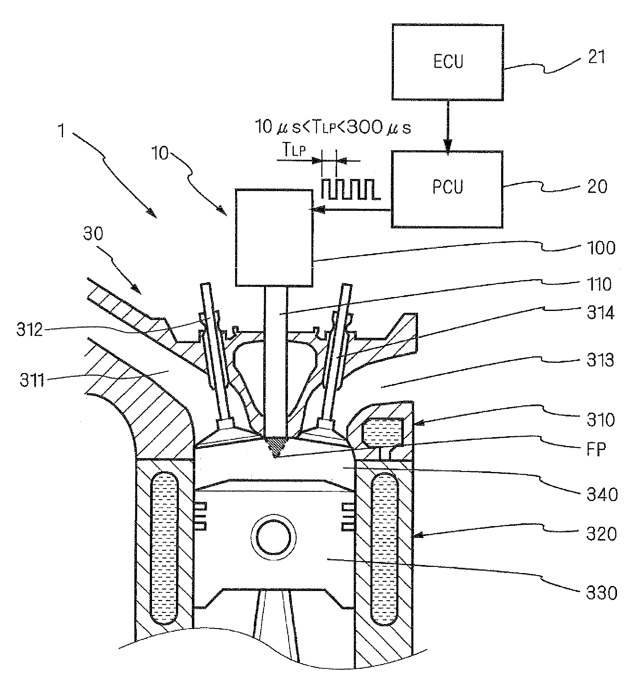
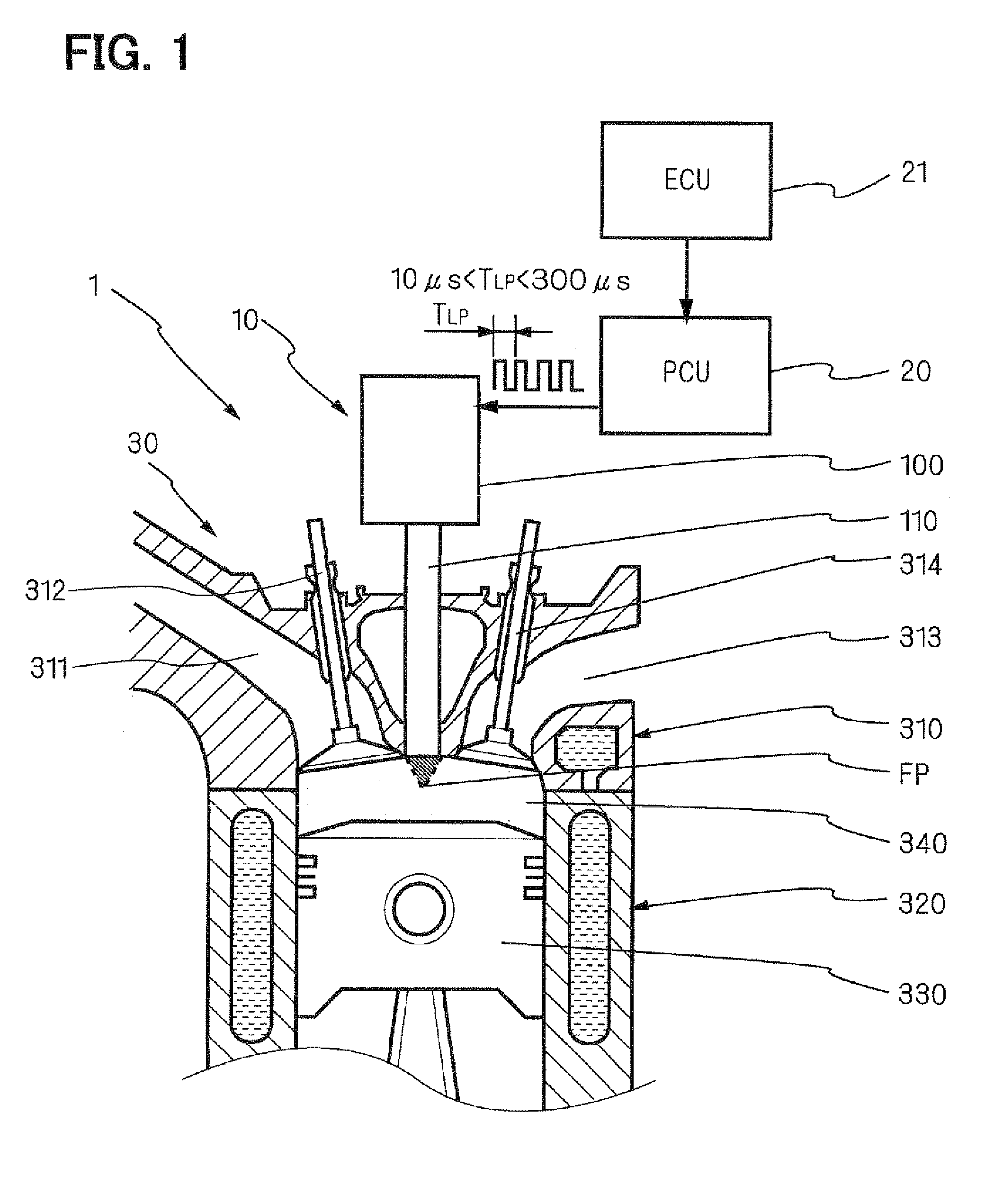
[0026]A laser ignition system 1 of one embodiment of the present invention will be described with reference to FIG. 1.

[0027]The laser ignition system 1 includes an internal combustion engine 30, a laser oscillator 10, an oscillation controller (PCU) 20, and an electronic control device (ECU) 21. The PCU 20 performs an oscillation control of the laser oscillator 10. In other words, the PCU 20 causes the laser oscillator 10 to generate laser pulses. The ECU 21 controls the PCU 20 and performs a combustion control of the internal combustion engine.

[0028]The internal combustion engine 30 includes a cylinder head 310, a cylinder 320, and a piston 330. A combustion chamber 340 is defined by an inner wall of the cylinder head 310, a radially inner wall of the cylinder 320, and an upper surface of the piston 330.

[0029]The cylinder head 310 is provided with an intake pipe 311 and an exhaust pipe 313. An intake valve 312 and an exhaust valve 314 enable and disable communication between the co...


PUM


Abstract

A laser ignition system includes a laser oscillator and an oscillation controller. The laser oscillator is configured to generate laser light into a combustion chamber of an engine. The oscillation controller is configured to cause the laser oscillator to generate a plurality of laser pulses into the combustion chamber in order to ignite the engine. The oscillation controller causes the laser oscillator to generate each of the plurality of laser pulses at a laser oscillation period that is longer than 10 μs and shorter than 300 μs.

Description

CROSS REFERENCE TO RELATED APPLICATION[0001]This application is based on and incorporates herein by reference Japanese Patent Application No. 2007-305743 filed on Nov. 27, 2007.BACKGROUND OF THE INVENTION[0002]1. Field of the Invention[0003]The present invention relates to the improvement of ignitability of a laser ignition system used for igniting an internal combustion engine, and relates to reduction of the laser ignition system in size.[0004]2. Description of Related Art[0005]Recently, in an internal combustion engine for vehicles, there has been needs for further improvement of fuel efficiency and leaner burn in order to reduce environmental load substances, such as nitrogen oxides, carbon monoxide, in combustion exhaust gas.[0006]There has been paid attention to a method for effectively causing combustion of lean air-fuel mixture by emitting laser light into a combustion chamber of the engine. In general, flame formed by a conventional ignition plug is limited from spreading i...

Claims


Application Information

Patent Timeline
Patent Type & Authority Applications(United States)
IPC IPC(8): F02P23/04
CPCF02P23/04
Inventor INOHARA, TAKAYUKIANDO, AKIHIROKIDO, NAOKI
Owner DENSO CORP
Why Eureka
Try Eureka