

Intake manifold for engine
a technology for intake manifolds and engines, applied in the direction of air intakes for fuel, combustion-air/fuel-air treatment, machines/engines, etc., can solve problems such as vibration noise, and achieve the effects of reducing the resistance of air taken into the engine, ensuring its rigidity, and smooth guiding
- Summary
- Abstract
- Description
- Claims
- Application Information
AI Technical Summary
Benefits of technology
Problems solved by technology
Method used
Image

Examples
Embodiment Construction
[0028]Descriptions will be provided for an embodiment of the present invention on the basis of the example of the present invention shown in the attached drawings.
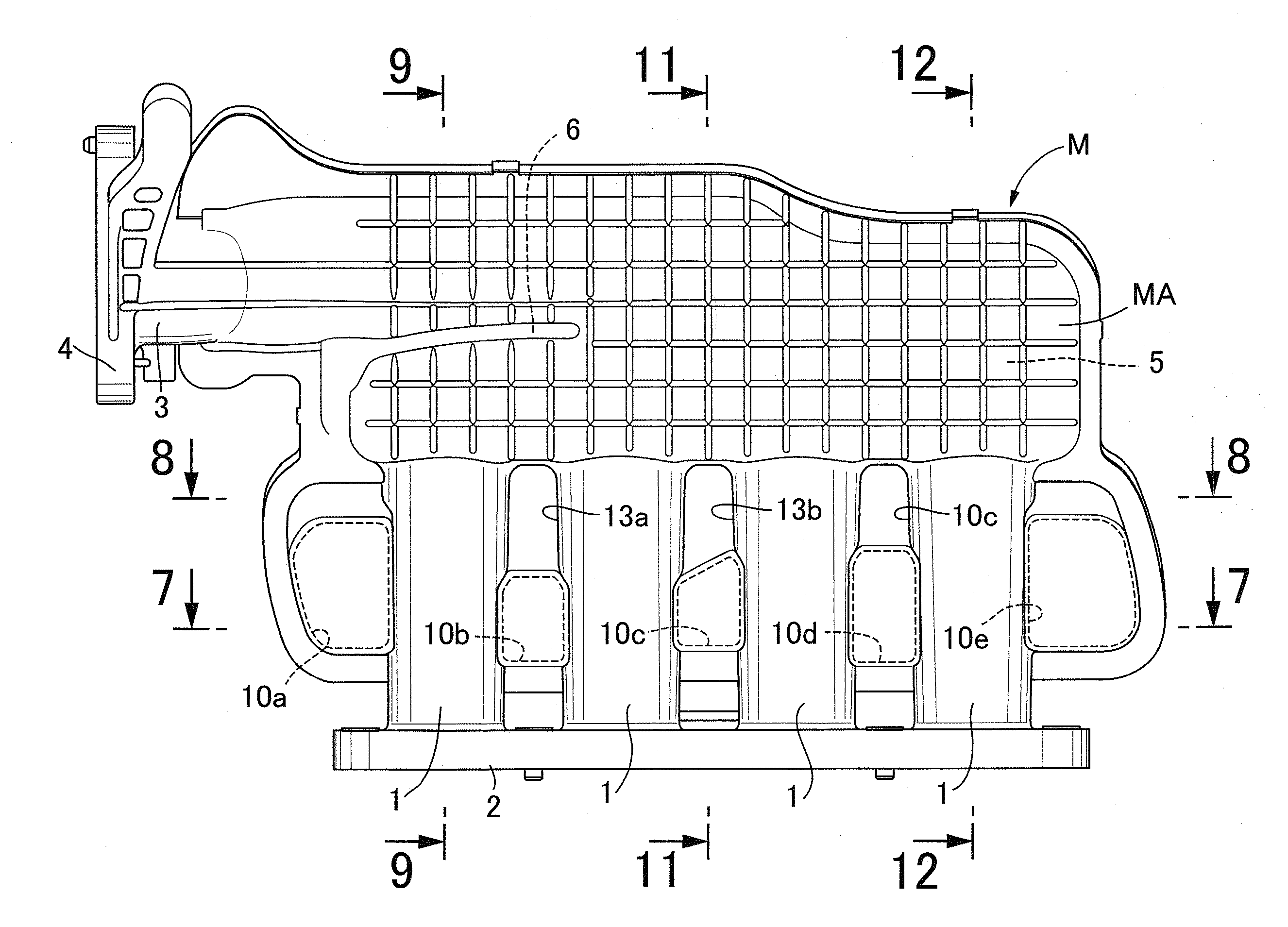
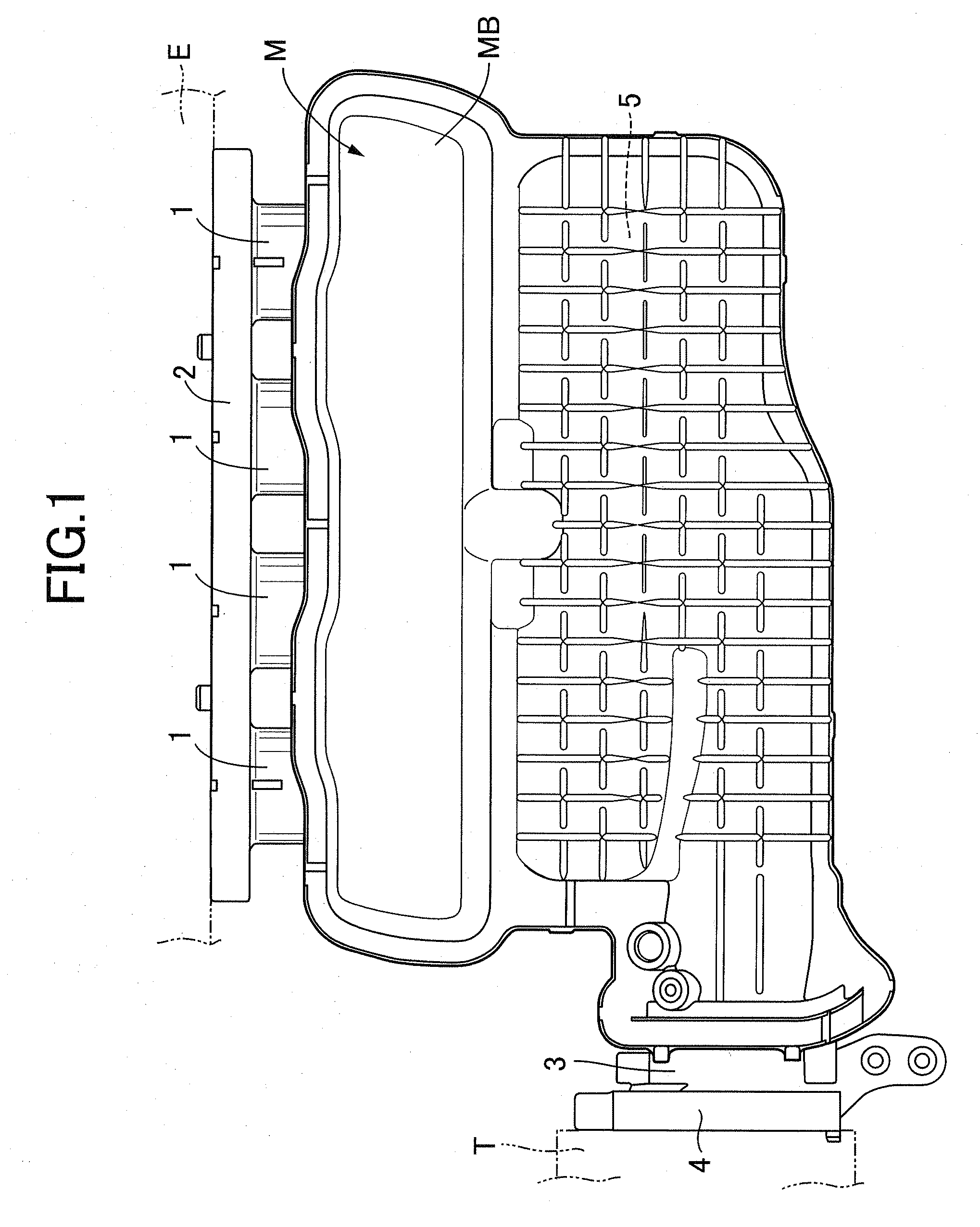
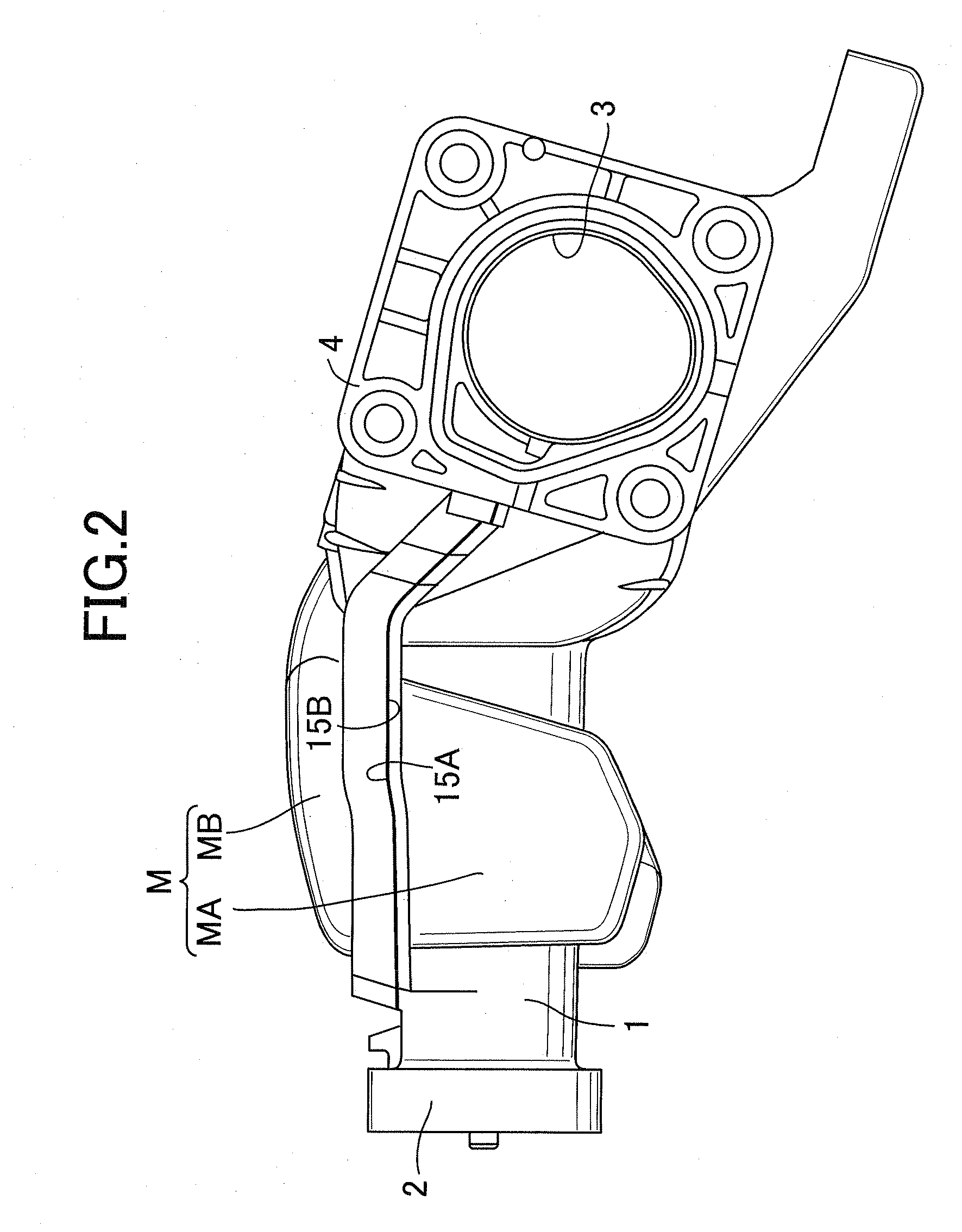
[0029]First of all, in FIGS. 1 to 3, reference numeral M denotes an intake manifold for a 4-cylinder engine E mounted on an automobile. This intake manifold M is shaped like a box whose longitudinal direction coincides with the left-right direction in FIG. 1. Four intake distribution pipes 1, 1 . . . which are arranged in a side-by-side relation to one another are formed along a side wall extending in the longitudinal direction. A common mounting flange 2 is integrally formed in the downstream ends of the intake distribution pipes 1, 1 . . . so as to integrally connect the intake distribution pipes 1, 1 . . . together. This mounting flange 4 is designed to be fixed to the engine E with multiple bolts.
[0030]An intake inlet pipe 3 is integrally formed in an end wall of the intake manifold M in a direction of arrangement of t...
PUM
 Abstract
Description
Claims
Application Information