Ionization vacuum device
- Summary
- Abstract
- Description
- Claims
- Application Information
AI Technical Summary
Benefits of technology
Problems solved by technology
Method used
Image

Examples
first embodiment
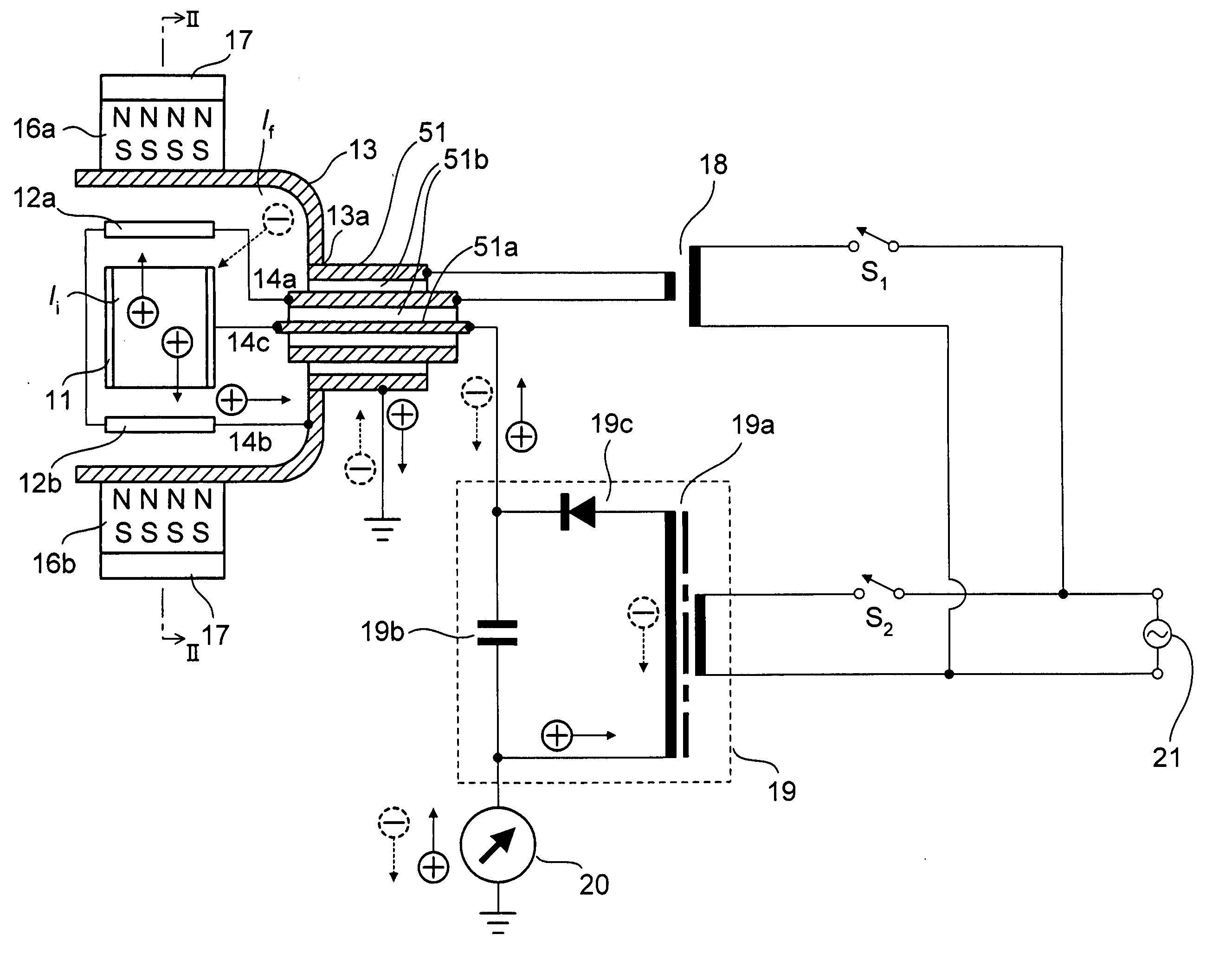
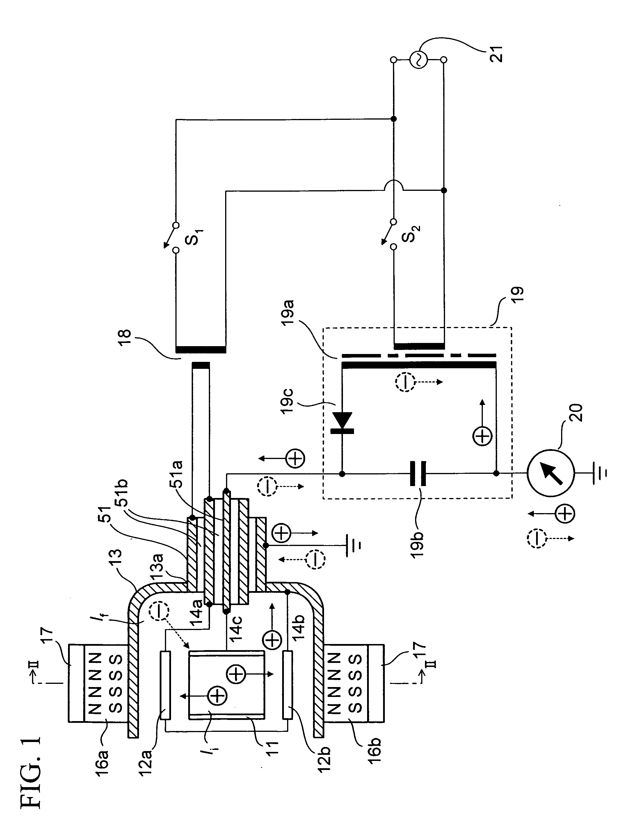
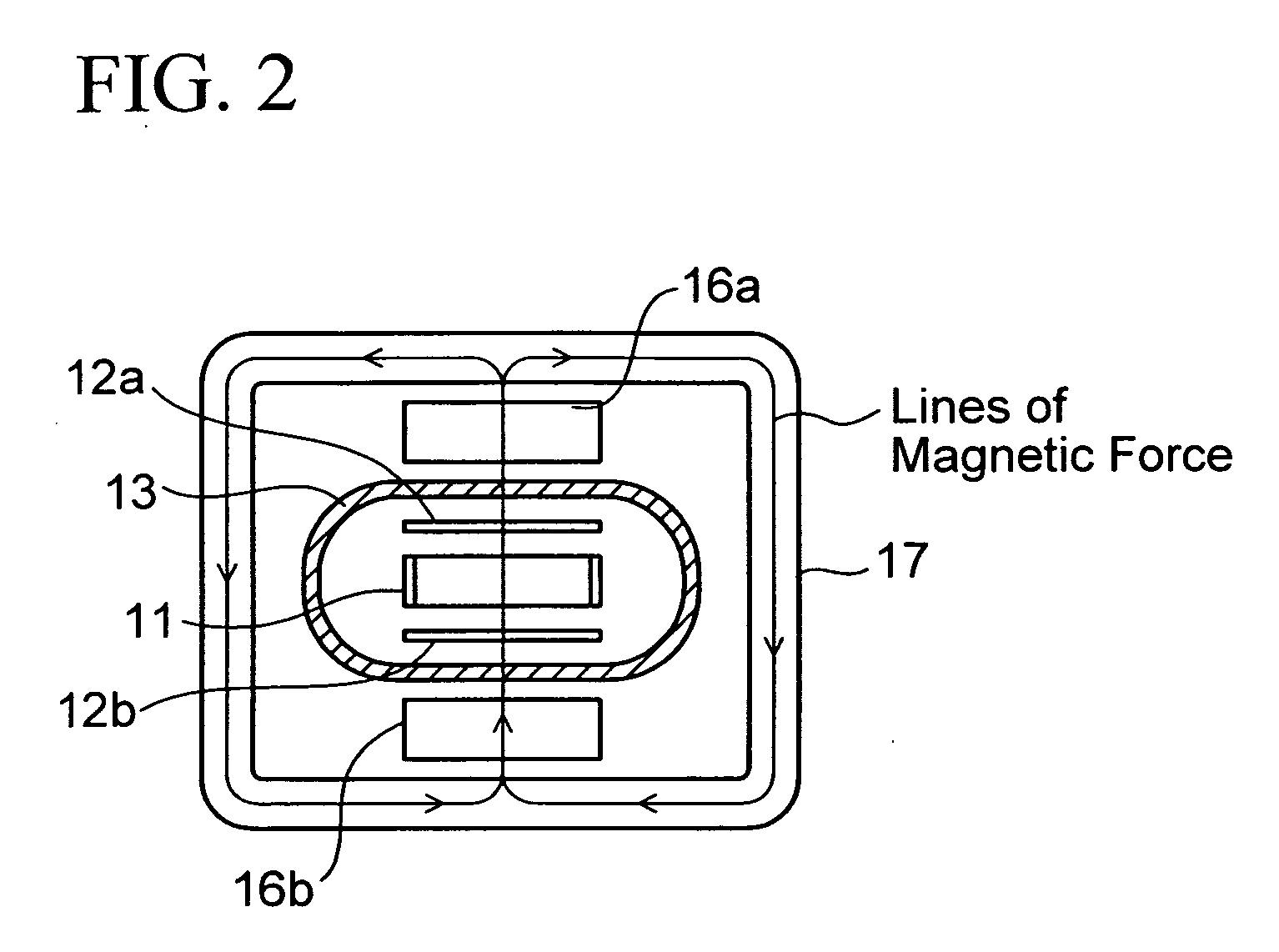
[0029]FIG. 1 is the schematic view of a single cell type ionization vacuum device according to the first embodiment of the present invention. The ionization vacuum device can be used as a Penning type sputter-ion pump as well as a cold cathode ionization vacuum gauge. FIG. 2 is the cross-sectional view taken along line II-II of FIG. 1.
[0030]In the ionization vacuum device of the first embodiment shown in FIG. 1, Penning Cell is housed in a vacuum vessel 13. The ionization vacuum device has a flange (not shown), and is intended to be attached via the flange to a vacuum vessel (vacuum vessel to be exhausted) of a vacuum treatment device that performs treatment in vacuum.
[0031]In the Penning Cell, a cylindrical anode 11 is arranged in the vacuum vessel 13 that is formed of a non-magnetic material, and plate-shaped cathodes (12a, 12b) are arranged so as to face two opening ends of the cylinder of the anode 11 and sandwich the anode 11 from above and below.
[0032]The vacuum vessel 13 has ...
second embodiment
[0059]FIG. 4 is the schematic view showing the constitution of the ionization vacuum device according to the second embodiment. FIG. 6B is an equivalent circuit of FIG. 4. The constitution of FIG. 4 and FIG. 6B is a constitution effective in removing the field emission current If from a discharge current flowing between the anode 11 and the cathodes (12a, 12b) in the case of including pressure measurement in a ultra high vacuum range.
[0060]The following points of the constitution of FIG. 4 are different in contrast with the constitution of FIG. 1 that the cathodes (12a, 12b) are severally connected to the power source 18 for heating (heating means) via the vacuum vessel 13 and the high voltage triaxial vacuum feedthrough 51 (via the terminal whose one end is grounded). Those points in FIG. 4 are a point that the cathodes (12a, 12b) are directly connected (without grounding) to the power source 18 for heating without interposing the vacuum vessel 13 and the high voltage triaxial vacu...
third embodiment
[0084]FIG. 7 is the perspective view showing the constitution of a cell 201 including the electrodes of a single cell type ionization vacuum device, which has a cathode of an inverted U-character shaped structure according to the third embodiment.
[0085]The single cell 201 having the electrode structure as shown in FIG. 7 is also called a magnetron cell. Note that the cell 201 is installed instead of the cell of FIG. 1 or FIG. 4, for example to constitute the ionization vacuum device. This ionization vacuum device can be used as at least one of a magnetron type sputter-ion pump and a cold cathode ionization vacuum gauge.
[0086]In the electrode shown in FIG. 7, points that are different from FIG. 4 are that a cathode 12c is in an inverted U-character shaped structure where a thin and long plate-shaped cathode material is bent into a U-character shape including two terminals and tip portions connecting with the two terminals, and that the electrode is equipped with a sputter-shield plat...
PUM
| Property | Measurement | Unit |
|---|---|---|
| Temperature | aaaaa | aaaaa |
| Temperature | aaaaa | aaaaa |
| Power | aaaaa | aaaaa |
Abstract
Description
Claims
Application Information
 - R&D
- Intellectual Property
- Life Sciences
- Materials
- Tech Scout
- Unparalleled Data Quality
- Higher Quality Content
- 60% Fewer Hallucinations
Browse by: Latest US Patents, China's latest patents, Technical Efficacy Thesaurus, Application Domain, Technology Topic, Popular Technical Reports.
© 2025 PatSnap. All rights reserved.Legal|Privacy policy|Modern Slavery Act Transparency Statement|Sitemap|About US| Contact US: help@patsnap.com