
Workspace enclosure system with automatic shut-off

Inactive Publication Date: 2009-05-28
CINARUCO INT
View PDF6 Cites 19 Cited by
  • Summary
  • Abstract
  • Description
  • Claims
  • Application Information

AI Technical Summary

Benefits of technology

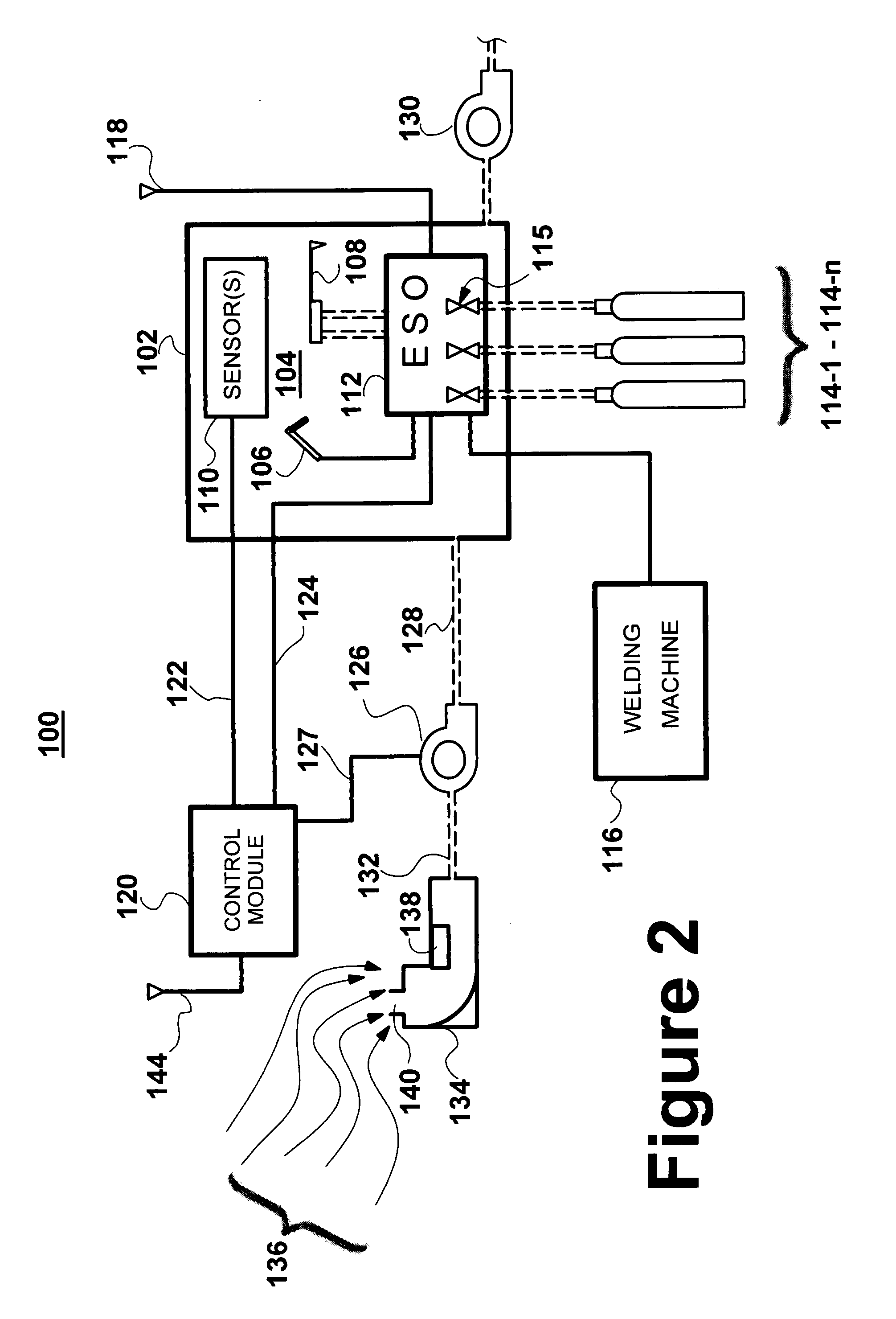
[0009]In accordance with one aspect of the invention, by disposing the emergency shut-off mechanism within the workspace enclosure, the need to take precautions concerning potential combustion outside of the enclosure due to the activation of solenoid valves or welding current switching circuitry is advantageously eliminated.
[0010]In accordance with another aspect of the invention, canisters containing the welding gases can be coupled directly to the emergency shut-off mechanism without the need for equipping the canisters with the necessary valves to control the delivery of welding gases. This means that the system may be implemented with a wider variety of welding equipment without the need for special retrofitting or modification to the welding equipment.
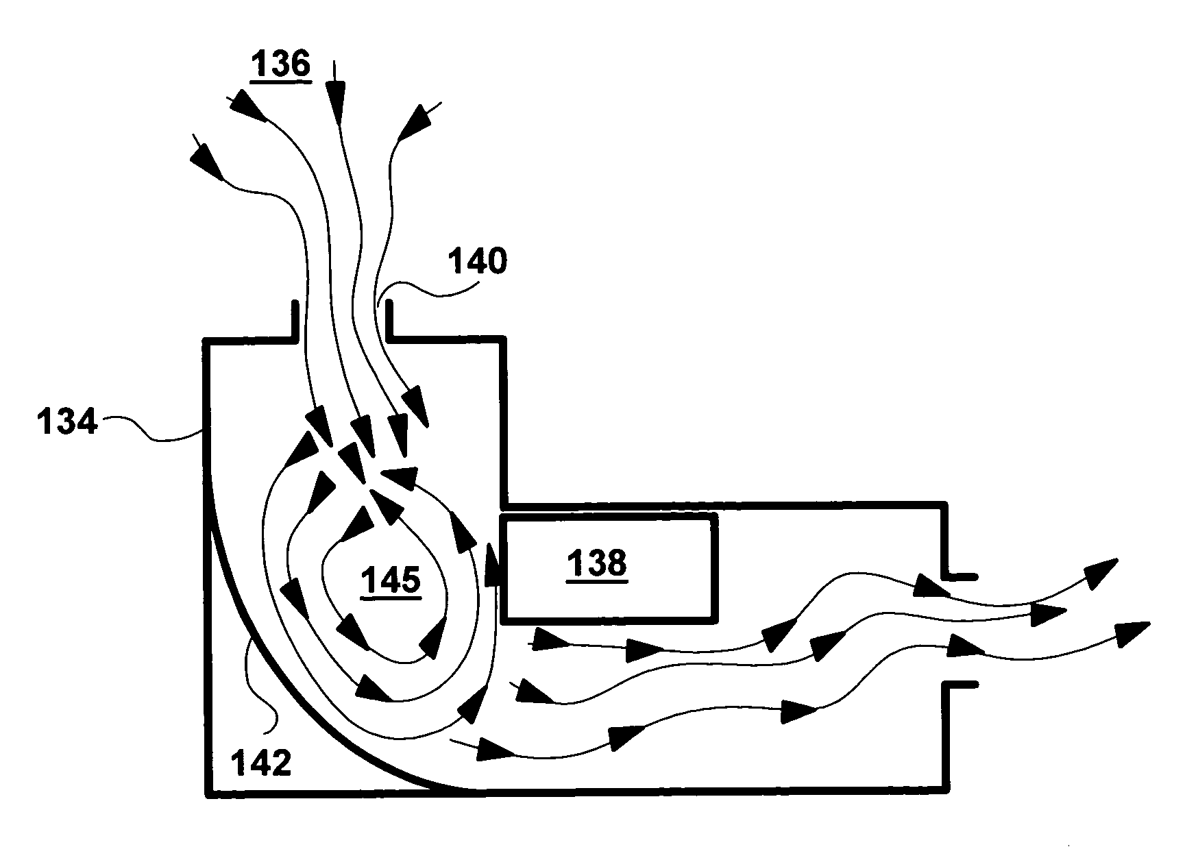
[0012]In one embodiment, the intake / sensor unit is configured with a baffle structure for creating eddy currents within the unit, thereby maximizing the exposure of air passing through the unit to the internal sensor(s).

Problems solved by technology

That is, no un-analyzed air can be sent into the enclosure.

Method used


Image

  • Workspace enclosure system with automatic shut-off
  • Workspace enclosure system with automatic shut-off
  • Workspace enclosure system with automatic shut-off

Examples


Embodiment Construction

[0017]In the disclosure that follows, in the interest of clarity, not all features of actual implementations are described. It will of course be appreciated that in the development of any such actual implementation, as in any such project, numerous engineering and technical decisions must be made to achieve the developers' specific goals and subgoals (e.g., compliance with system and technical constraints), which will vary from one implementation to another. Moreover, attention will necessarily be paid to proper engineering practices for the environment in question. It will be appreciated that such a development effort might be complex and time-consuming, but would nevertheless be a routine undertaking for those of ordinary skill in the relevant fields.

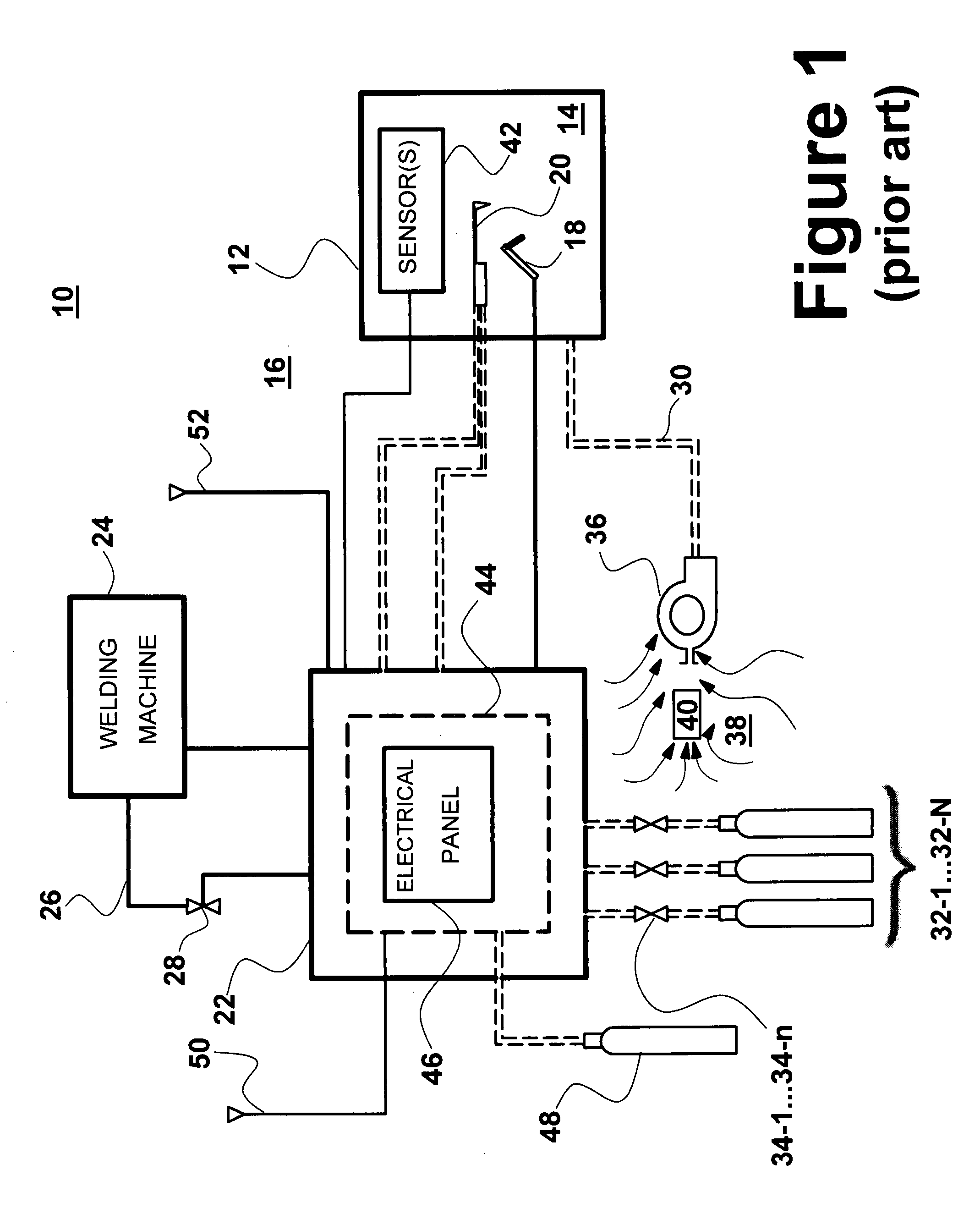
[0018]Referring to FIG. 1, there is shown a simplified schematic block diagram of a prior art workspace enclosure system 10 and illustrating certain features and aspects thereof, some of which may be perceived by some to be undesirabl...


PUM

PropertyMeasurementUnit
Pressureaaaaaaaaaa
Flow rateaaaaaaaaaa
Currentaaaaaaaaaa

Abstract

An emergency shut off system for a workspace enclosure system, wherein the shutoff system comprises an emergency shut-off module disposed within a workspace enclosure. A plurality of sensors are disposed within the workspace enclosure to detect the presence of undesirable gases or other undesirable conditions within the workspace enclosure. A control module external to the workspace enclosure is coupled to receive output signals from the plurality of sensors, and in response thereto to selective initiate a shut-down of operations taking place within the enclosure. In one example, the control module sends control signals to the emergency shut-off module causing the latter to close one or more valves restricting the flow of gases from external gas supply canisters. A blower is provided to create a flow of air into the enclosure, thereby maintaining a positive pressure within the enclosure. An air intake / sensor module is connected via a closed conduit or the like to the intake of the blower. The intake / sensor module includes a sensor for detecting the presence of gases or other undesirable conditions of incoming air, prior to said air reaching the intake of the blower. The control module is responsive to signals from the sensor in the intake / sensor module to deactivate the blower, thereby preventing undesirable gases to be delivered to the interior of the enclosure. In one embodiment, a baffle is provided within the intake / sensor module for enhancing the effectiveness of the sensing operation by minimizing the amount of incoming air that is not exposed to the sensor prior to being delivered into the enclosure.

Description

FIELD OF THE INVENTION[0001]The present invention relates generally to enclosures for working environments, and more particularly relates to a system and methodology for avoiding unsafe conditions in and around such enclosures.BACKGROUND OF THE INVENTION[0002]There are various settings in which it is necessary or desirable to provide a barrier between a particular working environment and the area surrounding it. Such settings are typically industrial in nature, and a prominent example of such is found on oil and gas drilling facilities, such as offshore platforms, production facilities and the like, in which industrial activities of various sorts regularly occurs in close proximity to areas in which the activity would be considered dangerous, or in which the environment in general is not suited to performing certain activities.[0003]In the case of offshore drilling platforms, it is very common for welding operations to be performed. Welding, of course, involves the generation of ext...

Claims


Application Information

Patent Timeline
IPC IPC(8): G08B21/00
CPCB23K37/006B23K31/02
Inventor WARDLAW, III, LOUIS J.
Owner CINARUCO INT
Learn More