Polarizing plate with optical compensation layer and image display apparatus using the same

a technology of optical compensation layer and polarizing plate, which is applied in the direction of polarizing elements, thin material handling, instruments, etc., to achieve excellent hardness, excellent abrasion resistance, and reduce thickness

Inactive Publication Date: 2009-05-28
NITTO DENKO CORP
View PDF7 Cites 44 Cited by
  • Summary
  • Abstract
  • Description
  • Claims
  • Application Information

AI Technical Summary

Benefits of technology

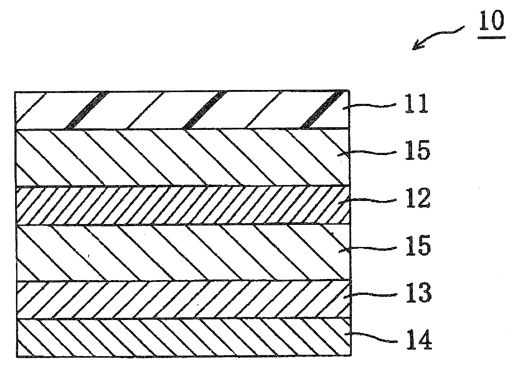
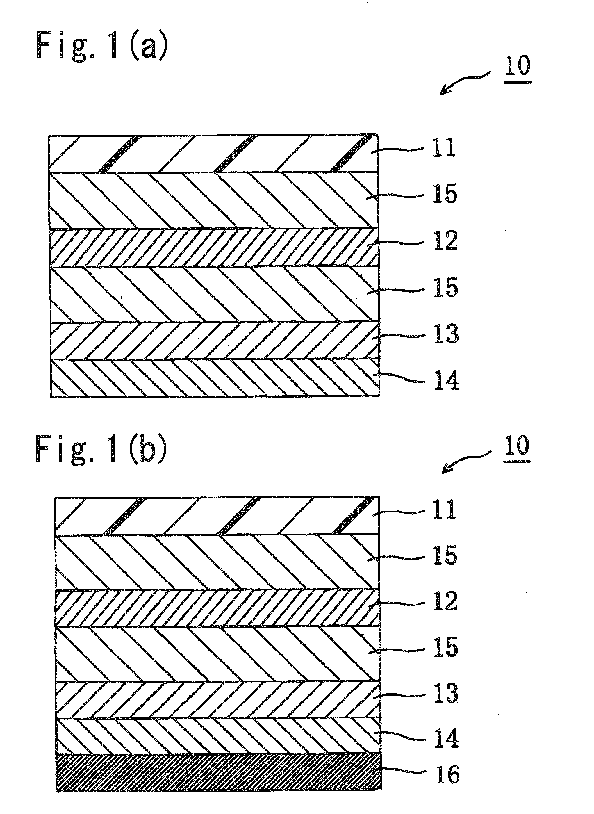
[0020]As described above, by allowing a hardcoat layer to contain urethaneacrylate, polyol (meth)acrylate, and (meth) acrylic polymer having an alkyl group containing at least two hydroxyl groups, a polarizing plate with an optical compensation layer that does not require a cover plate, contributes to the reduction in thickness, and is excellent in abrasion resistance and moist heat resistance can be obtained. It is presumed that, due to the presence of those resins, the hardcoat layer has an excellent hardness, whereby cracks, curls, and the deterioration in shrinkage on curing and in flexibility are prevented. Thus, the hardcoat layer in the present invention has excellent abrasion resistance and heat moist resistance, so it can replace a cover plate made of glass or a thick plastic sheet. The hardcoat layer in the present invention (preferably having a thickness of 15 to 50 μm) is remarkably thinner than the above-mentioned glass (thickness: about 0.5 mm) used in a liquid crystal display apparatus and the like, so the hardcoat layer can greatly contribute to the reductions in thickness and weight in a liquid crystal display apparatus and the like.
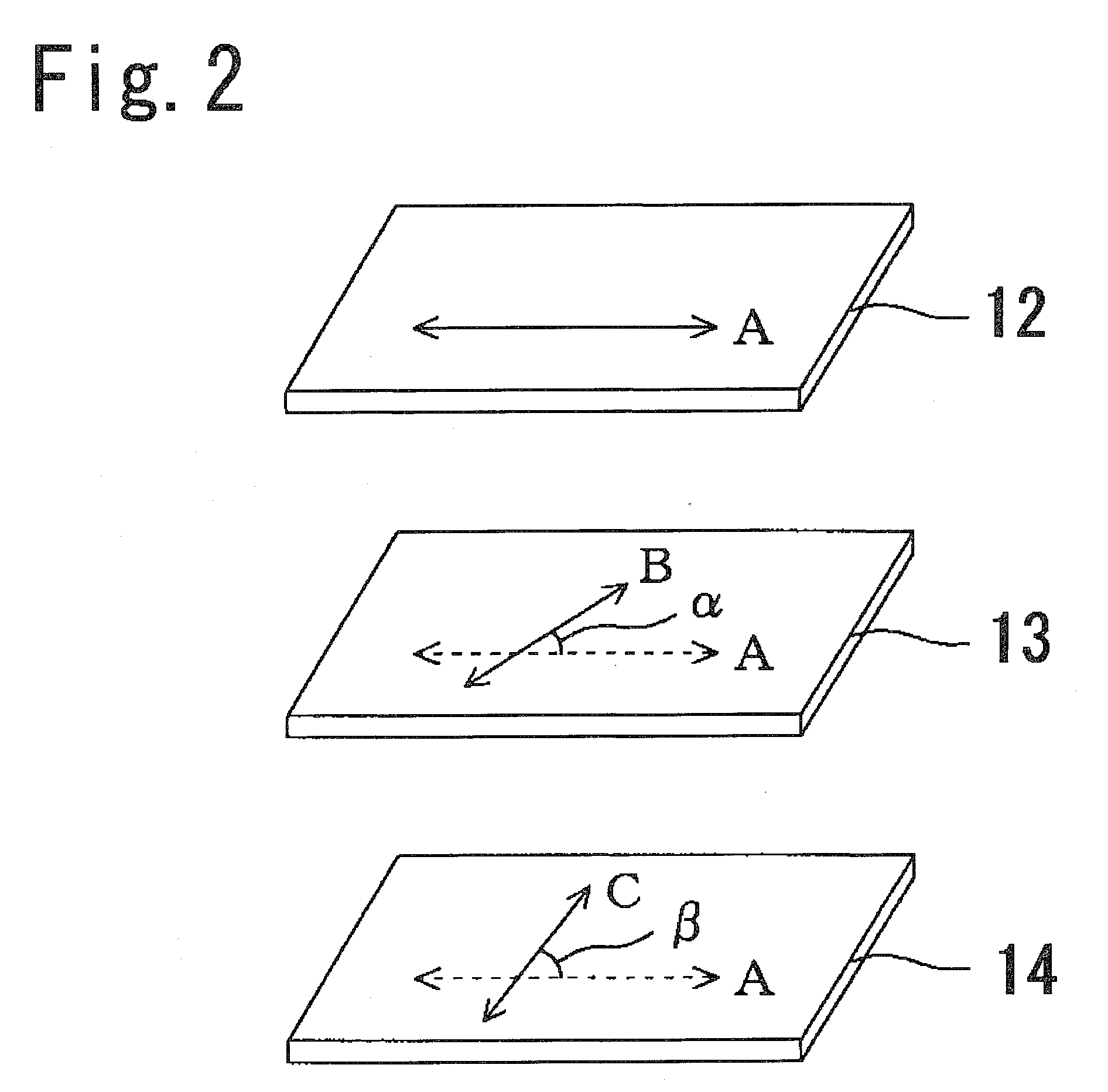
[0021]Further, the absorption axis of the polarizer and the slow axes of the first optical compensation layer (substantially a λ / 2 plate) and the second optical compensation layer (substantially a λ / 4 plate) are placed so as to intersect with each other. Therefore, in a liquid crystal display apparatus, particularly of a TN mode, an ECB mode, or a VA mode, a polarizing plate with an optical compensation layer that has excellent viewing angle compensation, exhibits circularly polarized light in a wide band, and suppresses light leakage in a black display can be obtained. Further, each of a first optical compensation layer and a second optical compensation layer may have an absolute value of a photoelastic coefficient in a predetermined range, so it can suppress a change in a retardation value caused by shrinkage stress during heating, and hence, heat non-uniformity can be prevented satisfactorily.

Problems solved by technology

However, in middle and small-sized liquid crystal display apparatuses required to be reduced in thickness and weight, it is not preferred to provide such a cover plate.

Method used


Image

  • Polarizing plate with optical compensation layer and image display apparatus using the same
  • Polarizing plate with optical compensation layer and image display apparatus using the same
  • Polarizing plate with optical compensation layer and image display apparatus using the same

Examples


example 1

Production of a Hardcoat Layer

[0200]First, 100 parts of urethane acrylate composed of pentaerythritol-based acrylate and hydrogenated xylenediisocyanate as urethane acrylate (herein after, referred to as A component), 49 parts of dipentaerythritol hexaacrylate (herein after, referred to as B1 component), 41 parts of pentaerythritol tetraacrylate (herein after, referred to as B2 component), and 24 parts of pentaerythritol triacrylate (herein after, referred to as B3 component) as polyol (meth)acrylate (herein after, referred to as B component), and 59 parts of a (meth) acrylic polymer having 2-hydroxyethyl group and 2,3-dihydroxypropyl group as a (meth)acrylic polymer having an alkyl group containing at least two hydroxyl groups (herein after, referred to as C component) were added. Then, 3 parts of a polymerization initiator (Irgacure 184) and 0.5 parts of a reactive leveling agent were mixed with respect to those total resin components, whereby a solid content of a hardcoat layer-f...

example 2

[0211]First, 100 parts by weight of urethane acrylate (herein after, referred to as A1 component) composed of pentaerythritol-based acrylate and isophorone diisocyanate as an A component, 59 parts by weight of a B1 component, 37 parts by weight of a B2 component, and 15 parts by weight of a B3 component as B components, 26 parts by weight of a (meth) acrylic polymer having a 2-hydroxyethyl group and a 2,3-dihydroxypropyl group as a C component, and 2 parts by weight of a polymerization initiator (Irgacure 184) with respect to the total resin components were used to produce a hardcoat layer in the same way as in Example 1. The thickness of the obtained hardcoat layer was 20 μm, and the pencil hardness thereof was 4H. A polarizing plate with an optical compensation layer was produced in the same way as in Example 1, except for using the obtained hardcoat layer.

example 3

[0212]A hardcoat layer was produced in the same way as in Example 1, except for using 100 parts by weight of the A1 component as an A component, 38 parts by weight of the B1 component, 40 parts by weight of the B2 component, and 16 parts by weight of the B3 component as B components, 30 parts by weight of a (meth) acrylic polymer having a 2-hydroxyethyl group and a 2,3-dihydroxypropyl group as a C component, and 3.5 parts by weight of a polymerization initiator (mixture of 1 part by weight of Irgacure 184 and 2.5 parts by weight of 2,4,6-trimethylbenzoinphenylphosphin oxide) with respect to the total resin components. The thickness of the obtained hardcoat layer was 20 μm, and the pencil hardness thereof was 4H. A polarizing plate with an optical compensation layer was produced in the same way as in Example 1, except for using the obtained hardcoat layer.


PUM

PropertyMeasurementUnit
thicknessaaaaaaaaaa
thicknessaaaaaaaaaa
thicknessaaaaaaaaaa

Abstract

The polarizing plate with an optical compensation layer of the present invention includes: a hardcoat layer; a polarizer; a first optical compensation layer placed so that a slow axis thereof intersects with an absorption axis of the polarizer; and a second optical compensation layer placed so that a slow axis thereof intersects with the absorption axis of the polarizer in the stated order, wherein: the first optical compensation layer provides a substantially ½ retardation with respect to a wavelength of monochromatic light; the second optical compensation layer provides a substantially ¼ retardation with respect to a wavelength of monochromatic light; and the hardcoat layer contains urethaneacrylate, polyol (meth)acrylate, and (meth) acrylic polymer having an alkyl group containing at least two hydroxyl groups. The polarizing plate with an optical compensation layer of the present invention may suitably be used for various image display apparatuses (such as a liquid crystal display apparatus and a self-luminous display apparatus).

Description

TECHNICAL FIELD[0001]The present invention relates to a polarizing plate with an optical compensation layer and an image display apparatus using the same. More specifically, the present invention relates to a polarizing plate with an optical compensation layer, which does not require a cover plate, contributes to the reduction in thickness, is excellent in abrasion resistance, moist heat resistance, and viewing angle compensation, exhibits circularly polarized light in a wide-band, prevents heat non-uniformity (heat fluctuation), and suppresses light leakage in a black display, and an image display apparatus using the polarizing plate with an optical compensation layer.BACKGROUND ART[0002]As one of image display apparatuses, there is known a liquid crystal display apparatus. Along with the technological innovations including wide viewing angle, high definition, high-speed response, and color reproducibility of the liquid crystal display apparatus, the application of the liquid cryst...

Claims


Application Information

Patent Timeline
Patent Type & Authority Applications(United States)
IPC IPC(8): G02F1/13363G02B5/30
CPCG02B5/3033G02B5/3083G02F1/133528G02F1/13363G02F2001/133638G02F2201/50Y10T428/105G02F2413/03G02F2413/08G02F2413/11G02F2413/12G02F2413/13G02F2202/40C09K2323/035G02F1/133634G02F1/133638G02B5/30
Inventor KITAMURA, YOSHITSUGUTAKADA, KATSUNORI
Owner NITTO DENKO CORP
Why Eureka
Try Eureka