Pattern formation method, pattern formation apparatus, exposure method, exposure apparatus, and device manufacturing method

Active Publication Date: 2009-05-28
NIKON CORP
View PDF12 Cites 11 Cited by
  • Summary
  • Abstract
  • Description
  • Claims
  • Application Information

AI Technical Summary

Benefits of technology

[0019]With this apparatus, the controller, to form a pattern with a size of a non-integer multiple of the modulation element on the object, changes at least one of the number and positions of modulation elements on the variable molding mask, which contributes to generation of patterns at least partia

Problems solved by technology

However, for the maskless-type exposure apparatus described above, it has been recently cleared to be difficult to obtain, particularly, a pattern with a size (i.e. line width) which is not equal to any of integer multiples of a size corresponding to

Method used


Image

  • Pattern formation method, pattern formation apparatus, exposure method, exposure apparatus, and device manufacturing method
  • Pattern formation method, pattern formation apparatus, exposure method, exposure apparatus, and device manufacturing method
  • Pattern formation method, pattern formation apparatus, exposure method, exposure apparatus, and device manufacturing method

Examples


Example

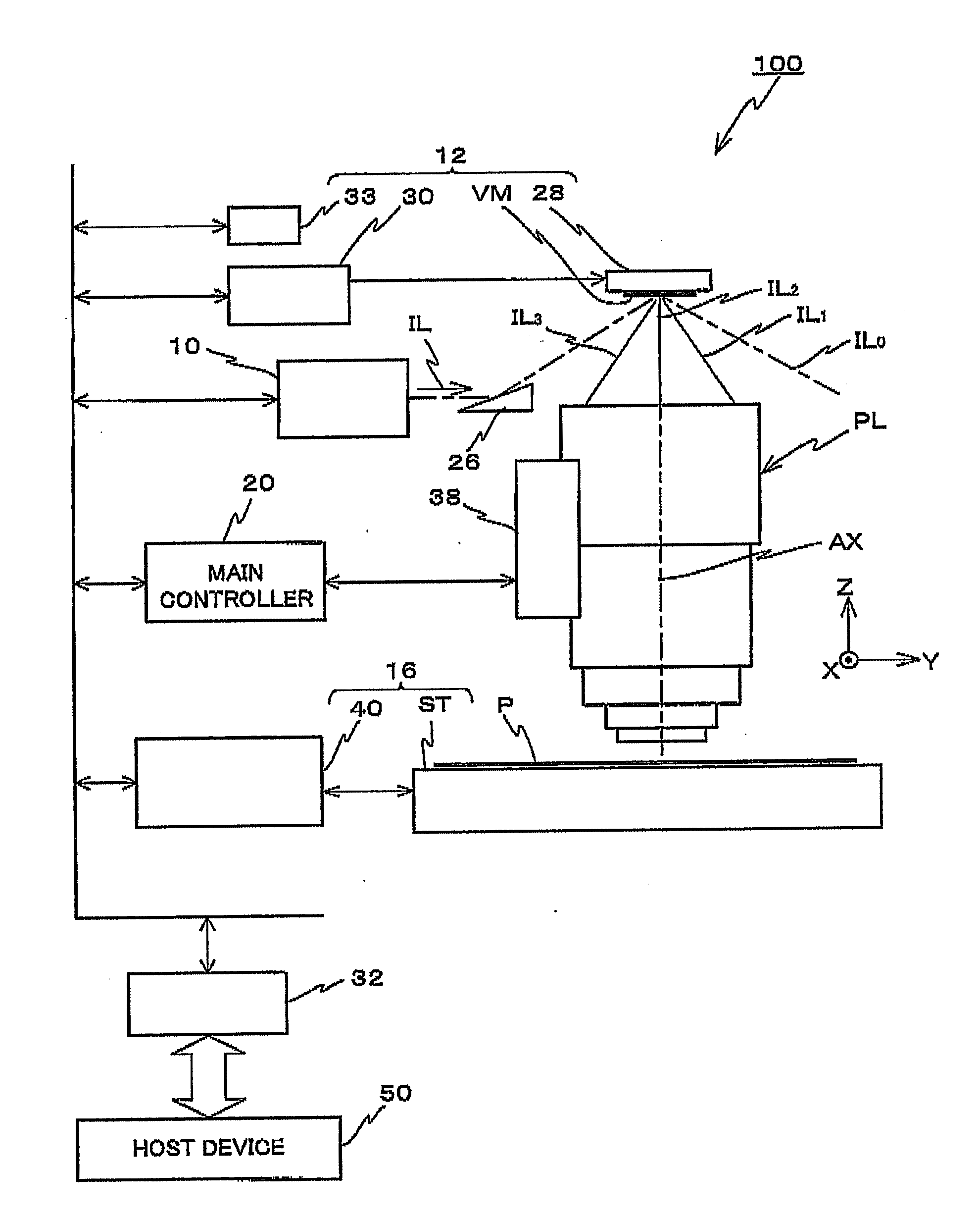
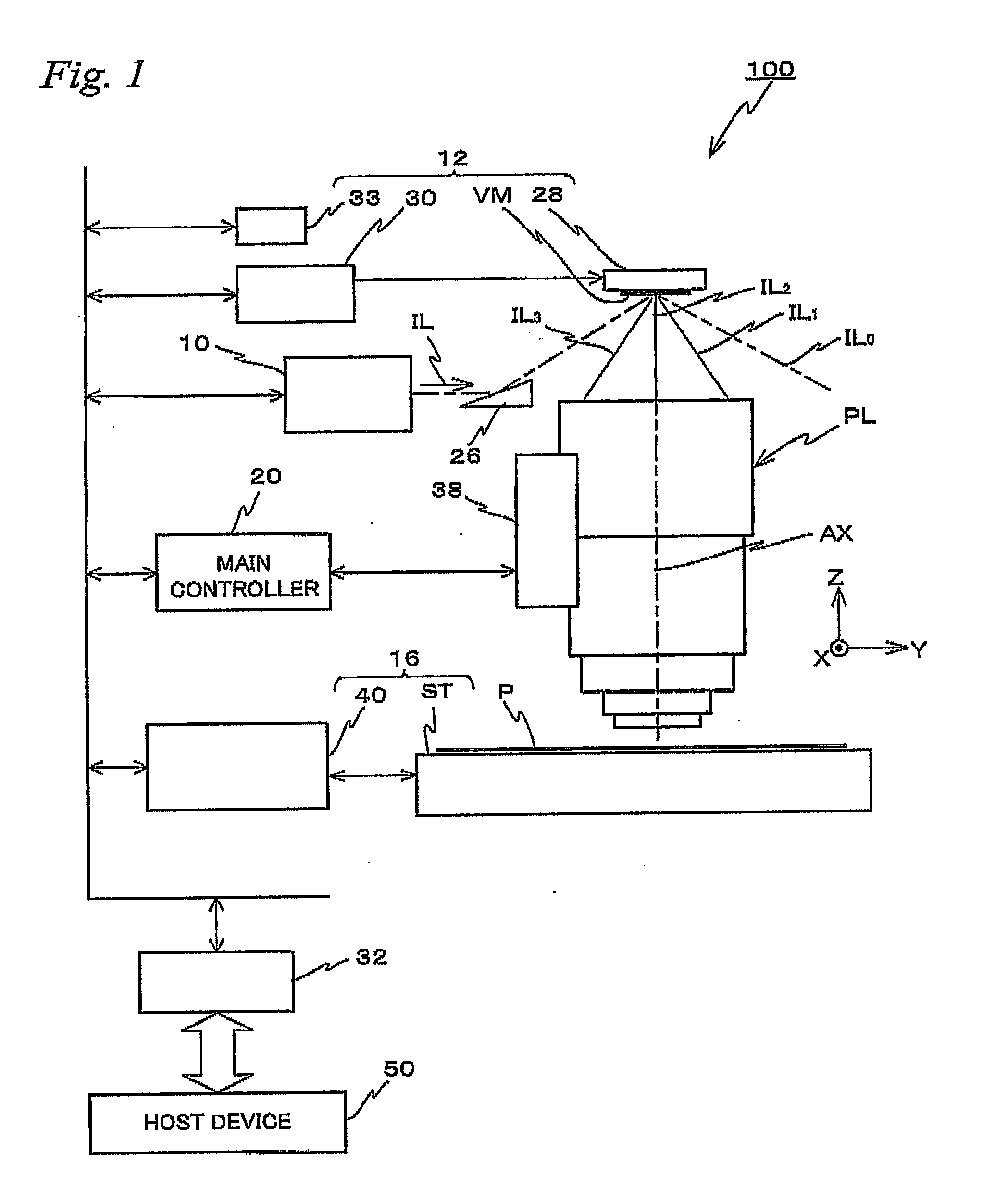
[0039]Hereinafter, descriptions are made for the first embodiment of the present invention based on FIG. 1 to FIG. 11. FIG. 1 schematically shows a constitution of an exposure apparatus 100 according to the first embodiment.

[0040]The exposure apparatus 100 is equipped with an illumination system 10, a pattern generation device 12, a projection optical system PL, a stage device 16, a control system that controls these devices and systems, and the like. The exposure apparatus 100 performs an exposure process by projecting an image of a pattern, which is generated by the pattern generation device 12, on a plate (sensitive substrate) P mounted on a stage ST that constitutes a part of the stage device 16, via a projection optical system PL. Further, the exposure apparatus 100 is a scanning exposure apparatus that forms patterns on the plate P by synchronizing switching (changing) of a pattern generated by the pattern generation device 12 with movement of the plate P. In following descrip...

Example

Second Embodiment

[0092]Next, descriptions are given for the second embodiment of the present invention based on FIG. 12 to FIG. 15. Here, for constituent parts that are identical or equivalent to those in the first embodiment described above, the same marks are used, and their explanations are simplified or omitted.

[0093]As shown in FIG. 12, the exposure apparatus 100′ in the second embodiment is equipped with: two illumination systems (including the prisms 26a and 26b, respectively) 10a, 10b constituted similar to the illumination system 10 described above; two variable molding masks VM1, VM2 constituted similar to the variable molding mask VM described above illuminated, respectively, by illumination lights IL1, IL2 from the illumination systems 10a, 10b; and holders 28a, 28b that hold, respectively, the variable molding masks VM1, VM2. Although the prisms 26a, 26b, as described above, actually constitute a part of the illumination systems 10a, 10b, respectively, in FIG. 12 for co...


PUM


Abstract

A drive system determines a combination of basic patterns (type of basic patterns to be generated and the number of pulses of each basic pattern) based on design data of patterns and pattern combination information stored in a memory. Then, based on the determined result, each micro mirror of a variable molding mask is individually controlled such that a plurality of basic patterns are sequentially generated according to each of the number of pulses, and each basic pattern generated by the variable molding mask is sequentially image-formed on a plate via a projection optical system. Thus, a pattern with a desired line width corresponding to the design data is formed at a desired position on the object with a good accuracy.

Description

CROSS-REFERENCE TO RELATED APPLICATIONS[0001]This application is a continuation of International Application PCT / JP2007 / 061709, with an international filing date of Jun. 11, 2007, the disclosure of which is hereby incorporated herein by reference in its entirety, which was not published in English.BACKGROUND OF THE INVENTION[0002]1. Field of the Invention[0003]The present invention relates to a pattern formation method, a pattern formation apparatus, an exposure method, an exposure apparatus, and a device manufacturing method, more specifically to a pattern formation method and a pattern formation apparatus used to form patterns on an object, an exposure method and an exposure apparatus used to expose an object with an illumination light, and a device manufacturing method with the pattern formation method, the exposure method, or the exposure apparatus.[0004]2. Description of the Background Art[0005]Conventionally, in a lithography process for manufacturing electronic devices (micro...

Claims


Application Information

Patent Timeline
IPC IPC(8): G03F7/20G02B26/02
CPCG03F7/70283G03F7/70291H01L21/0275H01L21/0274G03F7/70508G03F7/70433G03F7/70441G03F7/70625
Inventor HIRUKAWA, SHIGERUOWA, SOICHI
Owner NIKON CORP
Why Eureka
Try Eureka