Rotary heat engine

a heat engine and rotary technology, applied in the field of heat engines, can solve the problems of large temperature differential, disadvantageous mechanical efficiency of types, etc., and achieve the effect of reducing mechanical energy loss, prolonging engine service life, and improving reliability

Inactive Publication Date: 2009-06-04
VINCI SA +1
View PDF11 Cites 12 Cited by
  • Summary
  • Abstract
  • Description
  • Claims
  • Application Information

AI Technical Summary

Benefits of technology

[0019]In the just described embodiment, the power transmission mechanism for coupling the rotatable shaft of the rotor to the output shaft of the electrical generator is preferably comprised of a magnetic coupling system including a pair of magnetically cooperating coupling members. The pair of magnetic coupling members are joined together in non-contacting state for synchronous rotation of their respective rotatable shafts. As opposed to direct coupling of two rotatable shafts, the magnetic coupling allows the magnetic coupling member attached to the rotatable shaft of the rotor of the heat engine to be enclosed within a chamber defined by the cylinder sidewall and thus leakage of the working fluid or ga

Problems solved by technology

The stirling engines of this type are thus disadvantageous in mechanical efficiencies.
However, they require

Method used


Image

  • Rotary heat engine
  • Rotary heat engine
  • Rotary heat engine

Examples


first embodiment

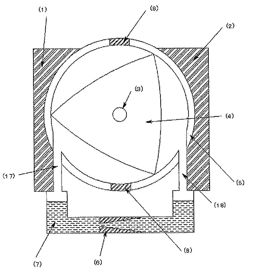
[0027]FIG. 1 shows schematically the structure of a rotary heat engine according the present invention. Referring to FIG. 1, the rotary heat engine comprises a cylinder (5) and a rotor (4) having generally triangular shape rotatably housed within the cylinder. A heat receiving section (1) and a heat discharging section (2) are disposed on the opposite sides of the cylinder integrally with or in thermal contact with the cylinder wall. The cylinder wall is circumferentially interrupted, at least in two zones, by a wall section made of heat insulating material (8) between the heat receiving section side and the heat receiving section side to thermally insulate between them. The rotor (4) is generally trianglar in shape in this embodiment. However, any rotor having other shapes such as a cross shape or having a curved face may also be used provided the rotor defines a plurality of spaces within which the gasified working fluid can be confined.

[0028]The engine also comprises a path for c...

third embodiment

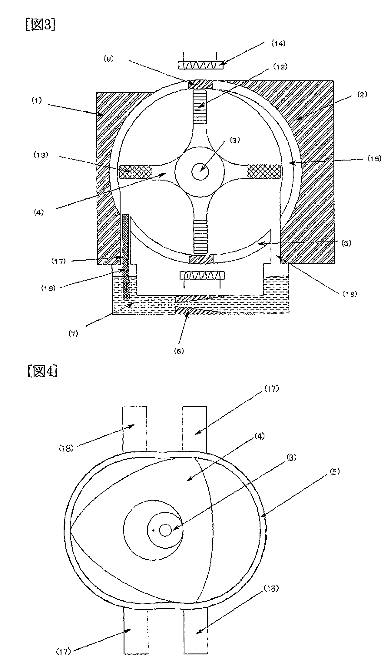
[0035]According to the present invention, the vaporization or gasifying of the working fluid staying in the reservoir section is accelerated with a bundle of capillary tubes (16) by the capillary attraction and the fluid contacting surface area of the cylinder inner wall in the heat discharging region is enlarged for improving the heat exchange efficiency. The above configurations contribute, in combination, to the provision of a rotary heat engine having a very high heat efficiency since a large volume change of the gasified working fluid is achieved even with a heat input stream having a relatively low temperature. Moreover, the electric power generation system including the above rotary heat engine in itself eliminates possible energy loss significantly resulting in a highly efficient electric power generating system. As a result, a nearly ideal stirling cycle may be attained by this embodiment.

fourth embodiment

[0036]FIG. 4 is an illustrative view of the rotary heat engine according the present invention showing schematically part of the internal structure of the engine having two sets of the working fluid inlet (17) and outlet (18) for conveying the working fluid to and from the cylinder (5). In this embodiment, the rotor (4) is generally triangular in shape and defines a circular opening concentrically. The periphery edge defining the central opening is toothed internally and the rotational shaft (3) rotatably carried between cylinder side walls is also toothed externally (not shown). The rotation of rotor (4) in the cylinder (5) is thus transmitted to the rotatable shaft (3) by the meshed engagement between the rotor (4) and the shaft (3). The rotary heat engine of this embodiment includes two sets or pairs of the working fluid inlet channel (17) and outlet channel (18) located opposite sides of cylinder. However, the inlet path (17) of the first set is juxtaposed with the outlet path (...


PUM


Abstract

A rotary heat engine having a cylinder and a rotor having a rotating shaft rotatably placed in the cylinder. The cylinder has a heat receiving section for supplying heat to the inside of the cylinder and a heat radiating section for radiating heat from the inside. The engine also has an engine section body and an operation liquid storage section. A vaporized gas supply channel and a gas recovery channel communicating with the inside of the cylinder are provided, respectively, on the heat receiving section side and heat radiating section side of the cylinder in the engine section body. The operation liquid storage section is between the vaporized gas supply channel and the gas collection channel in order to aggregate and liquefy recovered gas and is installed such that both channels fluidly communicate with each other. Also, the operation liquid storage section has a heat insulation dam provided with a through hole for preventing backflow of fluid flowing inside.

Description

TECHNICAL FIELD[0001]The present invention relates to a heat engine and, more specifically, to a rotary heat engine utilizing temperature differential.BACKGROUND ART[0002]Stirling engines have been known as an environment-friendly heat engine having a high heat efficiency in theory. Typically the stirling engine has a power piston called “displacer” that reciprocates in a cylinder. Improvements have been made on the stirling engine in recent years including, for example, a diaphragm mechanism.[0003]The stirling engines having a reciprocating displacer need provision for a mechanism for converting the reciprocating movement to the rotational movement of a drive shaft and a fly wheel in order to maintain rotation at a constant speed assisted by inertia. The stirling engines of this type are thus disadvantageous in mechanical efficiencies.[0004]An improved stirling engine is disclosed in JP 2003-83160A having a disc-shaped displacer capable of converting volume changes to rotating move...

Claims


Application Information

Patent Timeline
IPC IPC(8): F02G1/00F02B63/04
CPCF01C1/22F01C21/06F01C21/10F01K25/10Y02E20/14F02G1/043F04C2210/24F04C2240/30H02K7/1823F02B2053/005Y02P80/15
Inventor NAKASUKA, SHINICHISAHARA, HIRONORIHIGASHI, KENJI
Owner VINCI SA
Why Eureka
Try Eureka