Rotary electric machine

a rotary electric machine and rotor technology, applied in the direction of magnetic circuit rotating parts, magnetic circuit shape/form/construction, windings, etc., can solve the problems of reducing the thickness of the extending end portion limiting the cooling air flow supplied to the gap between the rotor iron core, and separating the fixing ring having reduced fixing force, so as to reduce the length of the retaining ring itself.

Inactive Publication Date: 2009-06-04
HITACHI LTD
View PDF6 Cites 4 Cited by
  • Summary
  • Abstract
  • Description
  • Claims
  • Application Information

AI Technical Summary

Benefits of technology

[0010]As described above, first, since the separation preventing device is provided between the rotor iron core and the retaining ring at the shrink-fitting position where the retaining ring is shrink-fitted to the rotor iron core, the retaining ring needs not to extend to the center portion of the rotor iron core in an axial direction, thereby reducing a length of the retaining ring itself. Accordingly, since it is possible to prevent the retaining ring from being adjacent to the end portion of the stator iron core, a gap between the rotor iron core and the stator iron core does not reduce. As a result, it is possible to ensure a cooling air flow between the rotor iron core and the stator iron core without enlarging the rotor.
[0011]Further, since the separation preventing device is provided at a position between the adjacent slots so as to be opposed to each other at the shrink-fitting position, the separation preventing device does not engage with the slot, thereby preventing the separation preventing device from interfering with the rotor coil in the slot or the insulating layer or the earth insulating layer between the rotor coils.

Problems solved by technology

As a result, when an axial thermal expansion is caused by a heat generated upon supplying current to the rotor coil for an operation thereof, a problem may arise in that the retaining ring having reduced fixing force is separated from the rotor iron core.
As a result, a gap between the end portion of the retaining ring and the end portion of the stator iron core becomes narrow, thereby limiting a cooling air flow supplied to a gap between the rotor iron core and the stator iron core.
However, when the inclined portion is provided, a thickness of the extending end portion of the retaining ring becomes smaller.
As a result, since stress is concentrated in the vicinity of a key groove for the separation preventing key provided in the retaining ring, a problem may arise in that a portion in the vicinity of the key groove is broken.
However, in this case, a problem arises in that a weight of the rotor iron core increases due to an increase in axial length of the rotor itself and a weight of the rotor coil increases due to an increase in axial length of the rotor coil.

Method used


Image

  • Rotary electric machine
  • Rotary electric machine
  • Rotary electric machine

Examples


first embodiment

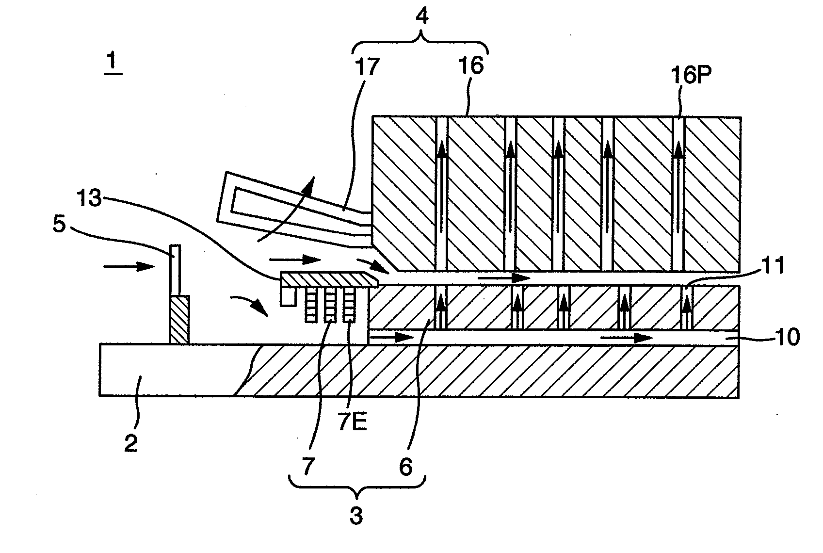
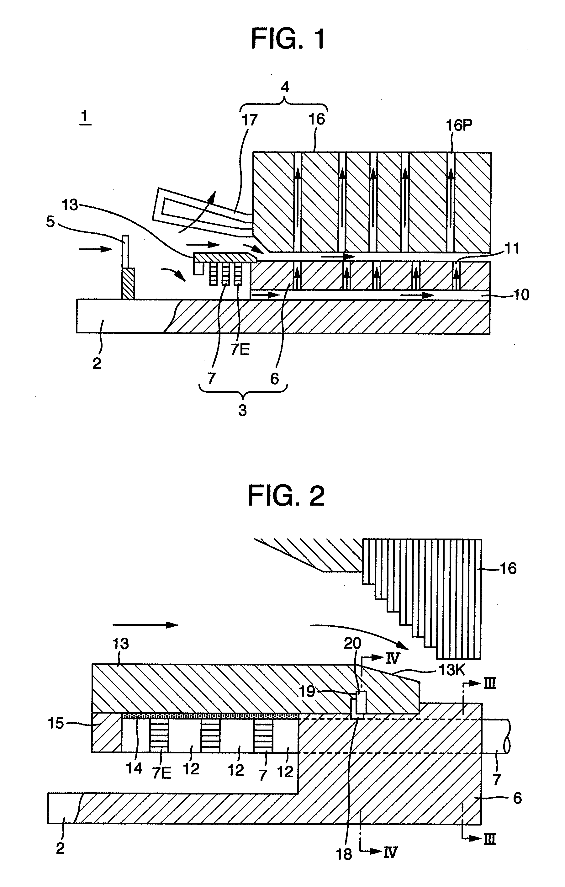
[0026]Hereinafter, a turbine generator according to the invention will be described with reference to FIGS. 1 to 6.

[0027]A turbine generator 1 mainly includes a rotor 3 provided in a rotary shaft 2, a stator 4 provided in the rotor 3 with a gap interposed therebetween, a blowing fan 5 blowing refrigerant for cooling the rotor 3 and the stator 4, a bearing (not shown) supporting the rotary shaft 2, and a stator frame (not shown) supporting the stator 4.

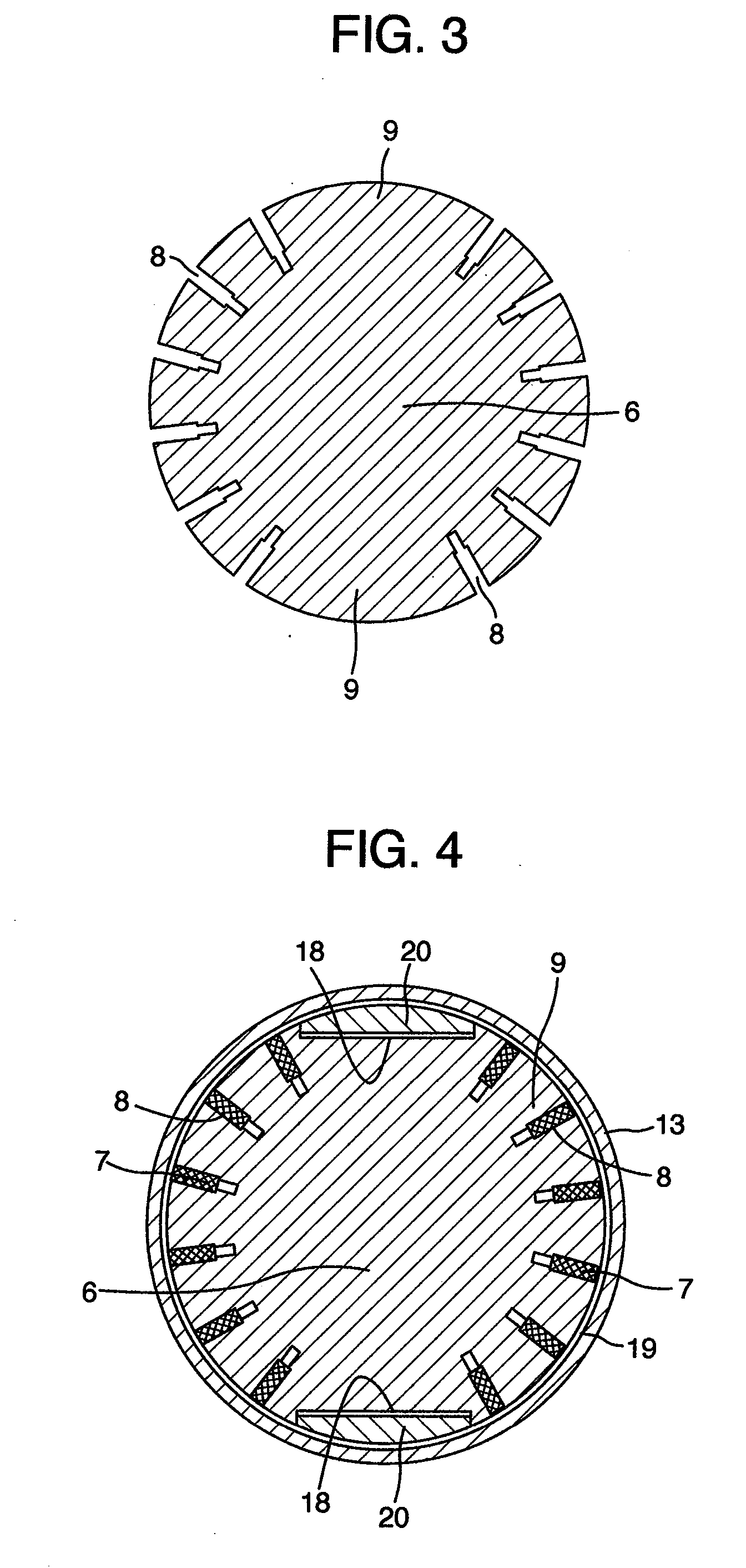
[0028]The rotor 3 includes a rotor iron core 6 configured as a lump-shape iron core and a rotor coil 7 mounted to the rotor iron core 6. The rotor iron core 6 is integrally formed with the rotary shaft 2 by casting or integrally fixed to the rotary shaft 2 by the use of a fixing member.

[0029]The rotor iron core 6 is configured such that a plurality of slots 8 is circumferentially provided in an axial direction and a rotor magnetic pole 9 is provided between slot groups each having the plurality of slots 8 adjacent to each other. The ro...

second embodiment

[0038]Next, a second embodiment according to the invention will be described with reference to FIGS. 7 and 8. Additionally, the same reference numerals are given to the same components shown in FIGS. 1 to 6, and the repetitive description thereof will be omitted.

[0039]The present embodiment is different from the first embodiment in that a cooling slot 21 is provided from the small-diameter portion at the shrink-fitting position of the stator iron core 6 toward the center in an axial direction. Also, the retaining ring 13 is shrink-fitted with the key 20 received in the first key groove 18, and then the key 20 is moved to the second key groove 19 of the retaining ring 13 by the use of the cooling slot 21, and, a fixed key 22 is inserted between the key 20 and a bottom of the first key groove 18 for the purpose of a fixing operation.

[0040]Likewise, when the key 20 is fixed by the fixed key 22 as a fixing member, it is possible to exhibit the same advantage as that of the first embodim...

third embodiment

[0041]A third embodiment according to the invention will be described with reference to FIGS. 9 and 10. Additionally, the same reference numerals are given to the same components shown in FIGS. 1 to 6, and the repetitive description thereof will be omitted.

[0042]The present embodiment basically has the same configuration as that of the second embodiment, but different from the second embodiment in that the key 20 is provided with a ventilating hole 23 communicating with the cooling slot 21 and an elastic plate spring 24 as a fixing member of the key 20 is fixed to a portion of the key 20 corresponding to the bottom of the first key groove 18 by the use of, for example, general methods such as welding or screw-fixing.

[0043]According to the present embodiment, it is possible to exhibit the same advantage as that of the first embodiment. Also, since the retaining ring 13 is shrink-fitted to the small-diameter portion of the rotor iron core 6, and then the key 20 is received in the seco...


PUM


Abstract

In a rotary electric machine, for ensuring a cooling air flow between a rotor iron core and a stator iron core without enlarging a rotor, a separation preventing device is provided at a position between adjacent slots so as to correspond to each other at a shrink-fitting position where a retaining ring is shrink-fitted to a rotor iron core. Since a separation preventing position of the retaining ring is located at the shrink-fitting position, it is possible to reduce a length of the retaining ring itself so as not to be adjacent to the end portion of the stator iron core. Accordingly, a gap between the rotor iron core and the stator iron core does not reduce. As a result, it is possible to ensure a cooling air flow between the rotor iron core and the stator iron core without enlarging the rotor.

Description

FIELD OF THE INVENTION [0001]The present invention relates to a rotary electric machine such as a steam turbine generator and a gas turbine generator, and more particularly, to a rotary electric machine in which a retaining ring retains a rotor coil end portion protruding from a rotor iron core.DESCRIPTION OF RELATED ART [0002]In general, since a turbine generator rotates at high speed, a large centrifugal force acts on a rotor coil end portion protruding from a rotor iron core in an axial direction. Therefore, in order to prevent the rotor coil end portion from being deformed by the large centrifugal force acting thereon, a high-tension steel retaining ring retains the rotor coil end portion in such a manner that the outer peripheral portion is shrink-fitted to the axial end portion of the rotor iron core.[0003]However, the retaining ring shrink-fitted to the end portion of the rotor iron core is enlarged in diameter by a centrifugal force acting on the rotor coil end portion or a ...

Claims


Application Information

Patent Timeline
Patent Type & Authority Applications(United States)
IPC IPC(8): H02K1/28H02K1/32
CPCH02K9/005H02K3/51H02K9/00
Inventor TANAKA, TAKAYASUMURAYAMA, HIROHIDEHATTORI, KENICHITAKAHASHI, KAZUHIKO
Owner HITACHI LTD
Why Eureka
Try Eureka