Vibration-Wave Detector

Inactive Publication Date: 2009-06-04
TOKYO ELECTRON LTD
View PDF3 Cites 17 Cited by
  • Summary
  • Abstract
  • Description
  • Claims
  • Application Information

AI Technical Summary

Benefits of technology

[0015]In the vibration-wave detector, according to the present invention, including the vibration plate and the plurality of resonators connected to the vibration plate and each resonating with a different specific frequency, the acoustic shielding section acoustically separates one of the surfaces of the vibration plate from the other surface to prevent the sound wave,

Problems solved by technology

As a result, it is difficult to maintain the pressure difference between the sound pressure applied on one of the surfaces of the diaphragm 2 and the sound pressure applied on the other surface, whereby

Method used


Image

  • Vibration-Wave Detector
  • Vibration-Wave Detector
  • Vibration-Wave Detector

Examples


Example

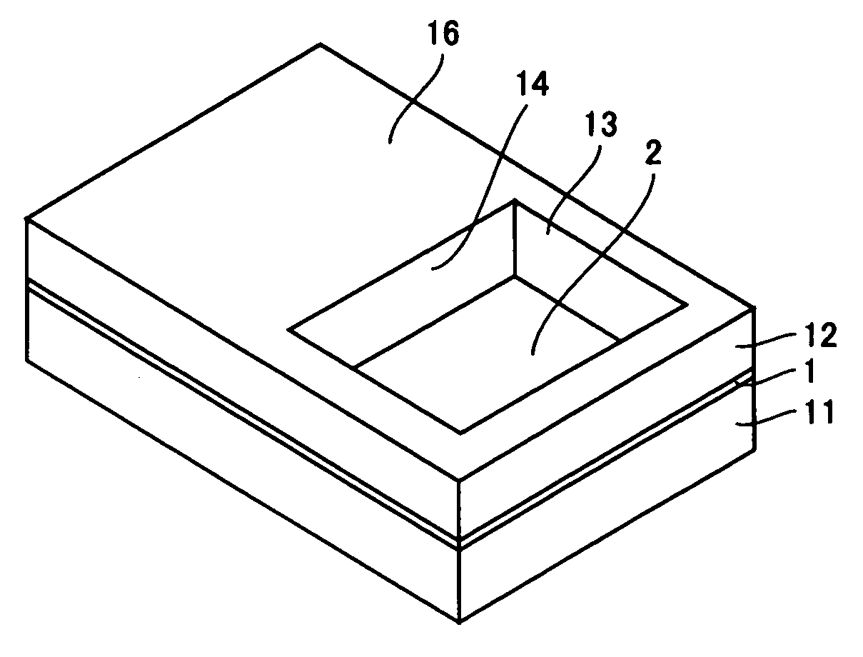
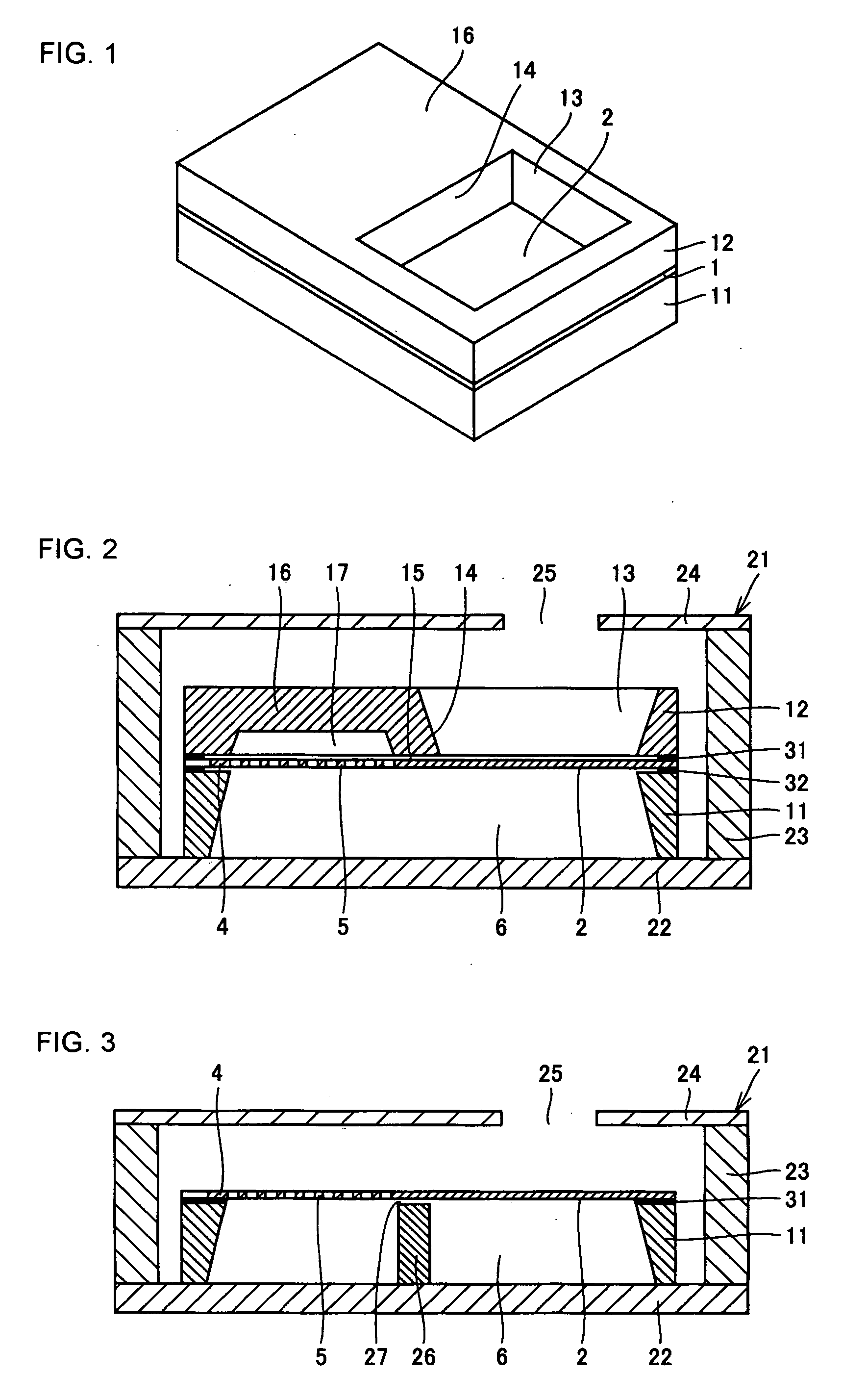
[0030]FIG. 1 is an external perspective view of a vibration-wave detector according to one embodiment of this invention with a cap 12 thereon. FIG. 2 is a cross-sectional view of the vibration-wave detector in FIG. 1 housed in a ceramic package 21.

[0031]In FIGS. 1 and 2, a sensor body 1 has almost the same structure as that shown in FIG. 8 and includes a diaphragm 2, a transversal beam (not shown), a terminator 4 and resonator beams 5 acting as a plurality of resonators. The sensor body 1 is placed on a supporter 11 that is a supporting member holding the periphery of the sensor body 1. A cap 12 is put on the sensor body 1. The sensor body 1, supporter 11 and cap 12 are housed within the ceramic package 21 as shown in FIG. 2.

[0032]The supporter 11 is made of, for example, silicon or glass, into a rectangular shape so as to surround the periphery of the lower surface of the sensor body 1, and has a backroom 6 inside thereof as a vacant room. The backroom 6 is made to secure a space f...


PUM


Abstract

A sensor body 1 having a plurality of resonator beams 5 each resonating with a different specific frequency and a plate-like diaphragm 2 connected to the resonator beams and vibrating in response to sound waves is supported by a supporter 11. A cap 12 for acoustically separating one of the surfaces of the diaphragm 2 from the other surface is placed on the sensor body 1 to make the pressure difference between the sound pressure applied on one of the surfaces of the diaphragm 2 and the sound pressure applied on the other surface large in order to improve sensitivity.

Description

TECHNICAL FIELD[0001]This invention relates to vibration-wave detectors. More specifically, this invention relates to a vibration-wave detector for electrically detecting the intensity of a vibration wave in each frequency band using a plurality of resonators with different resonant frequencies from each other.BACKGROUND ART[0002]FIG. 8 is a plan view of a conventional vibration-wave detector. This vibration-wave detector is disclosed in Japanese Patent No. 3348687. In FIG. 8, a sensor body 1 is formed on a semiconductor silicon substrate 10 and includes a diaphragm 2, a transversal beam 3, a terminator 4 and a plurality of resonator beams 5. The diaphragm 2 is a thin plate designed so as to vibrate in response to input sound waves. The transversal beam 3 couples the diaphragm 2 and terminator 4 and is wide on the diaphragm 2 side and gradually tapers toward the terminator 4 to be narrowest at an end of the terminator 4.[0003]The plurality of resonator beams 5 have adjusted lengths ...

Claims


Application Information

Patent Timeline
IPC IPC(8): H01L41/053
CPCG01H3/08H04R17/02H04R7/08H04R1/245G01H11/08G01H13/00
Inventor IKEUCHI, NAOKI
Owner TOKYO ELECTRON LTD
Why Eureka
Try Eureka