Multiple-Rotation Absolute-Value Encoder of Geared Motor

a technology of absolute value encoder and geared motor, which is applied in the direction of process and machine control, general control system, instruments, etc., can solve the problems of inefficiency and needing more time, and achieve the reduction of rotational speed of the gear shaft, simple configuration, and the effect of reducing the start-up tim

Active Publication Date: 2009-06-04
HARMONIC DRIVE SYST IND CO LTD
View PDF10 Cites 27 Cited by
  • Summary
  • Abstract
  • Description
  • Claims
  • Application Information

AI Technical Summary

Benefits of technology

[0016]The reduction mechanism preferably has a configuration having a magnetic gear comprising a multiple-pole magnet of four poles or more that rotates in association with the rotation of the first two-pole magnet, wherein the second two-pole magnet is attached to the shaft of the magnetic gear. The rotational speed of the gear shaft can be reduced in a non-contact state through the use of the magnetic gear, so that the gear shaft is not subjected to unnecessary loading. Merely increasing the number of magnetized poles of the magnetic gear and not adding any components allows the operating range of the load side device to be set so as to be an angular range of one or fewer rotations of the second two-pole magnet. The load side operating range can thus be accommodated through a very simple configuration.
[0017]Using the multiple-rotation absolute-value encoder of the present invention allows the machine starting point of the load side device to be determined without performing an additional start-up operation when the operation of the geared motor is started; therefore, the start-up time can accordingly be reduced.

Problems solved by technology

In a positioning operation for positioning at the starting point a load side device associated with a conventional geared motor, the motor shaft thus must be made to rotate multiple times, which is problematic in regard to requiring more time and being inefficient.

Method used


Image

  • Multiple-Rotation Absolute-Value Encoder of Geared Motor
  • Multiple-Rotation Absolute-Value Encoder of Geared Motor
  • Multiple-Rotation Absolute-Value Encoder of Geared Motor

Examples


Embodiment Construction

[0022]A description is provided hereunder of one embodiment of a geared motor comprising a multiple-rotation absolute-value encoder to which the present invention has been applied, with reference being made to the accompanying drawings.

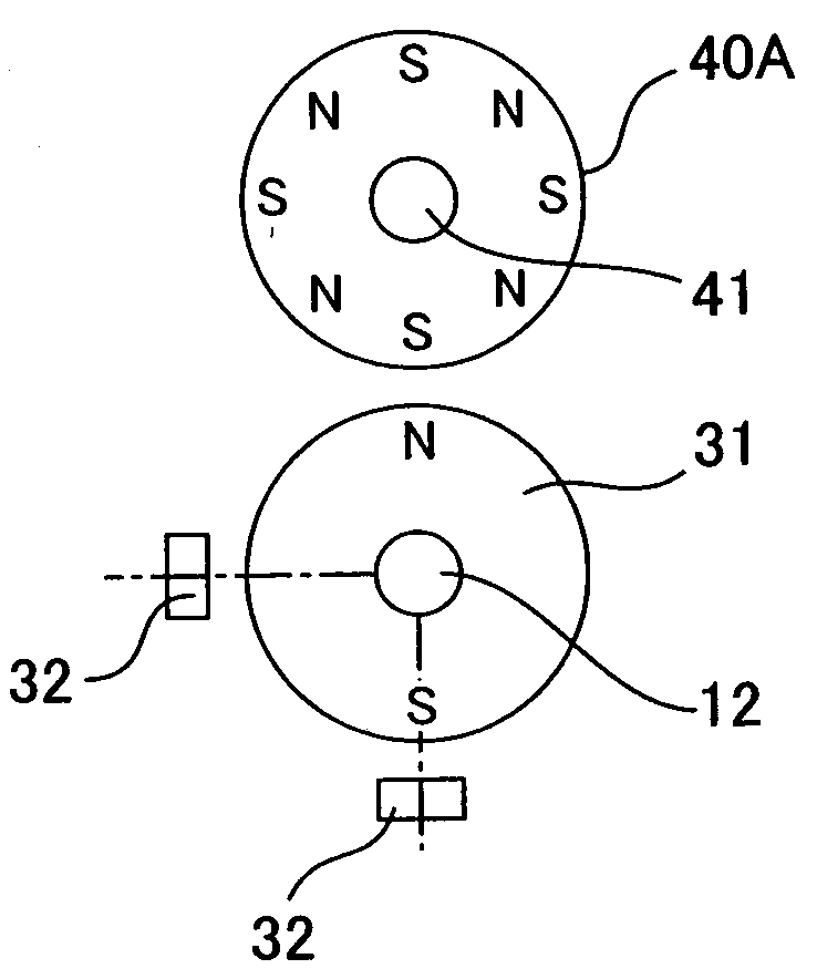
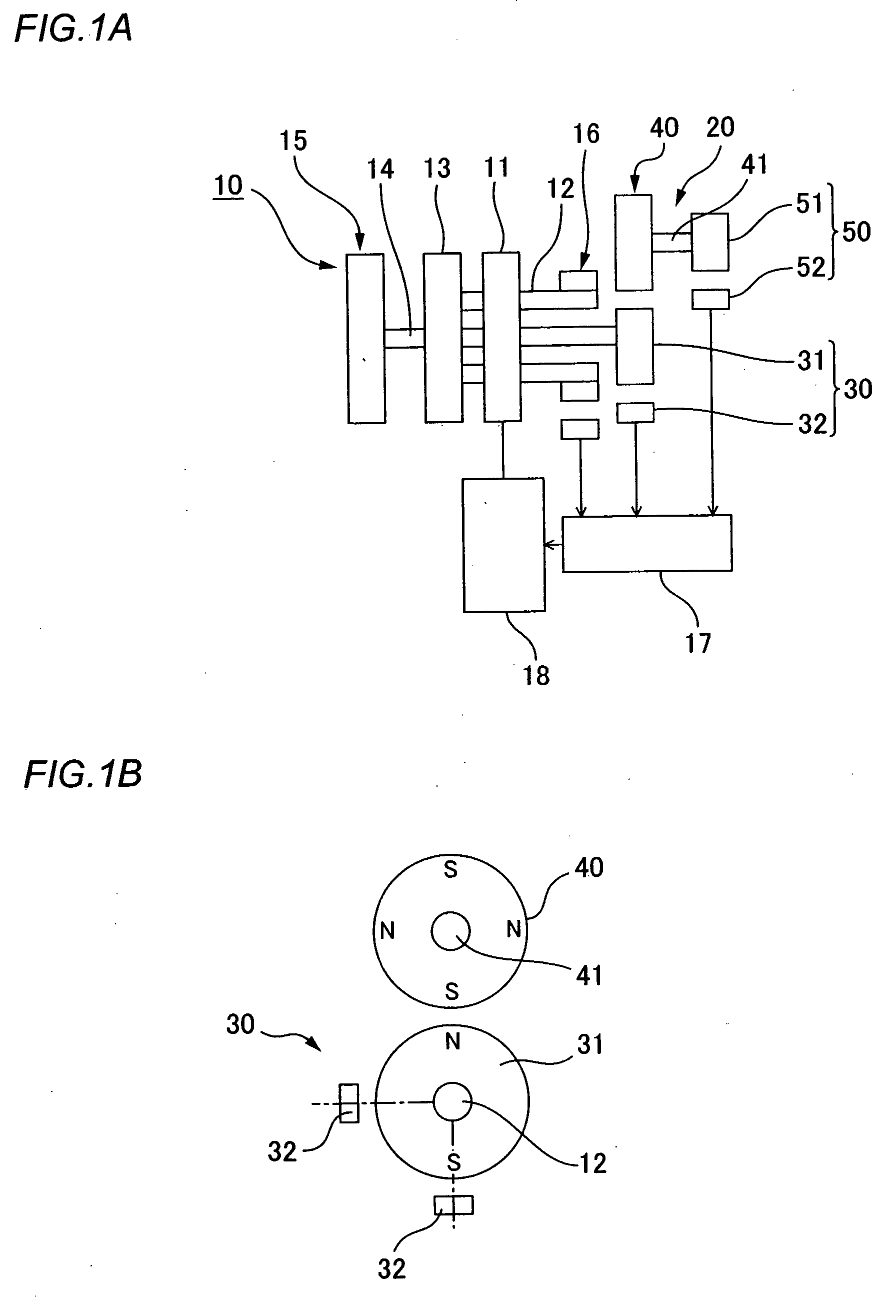
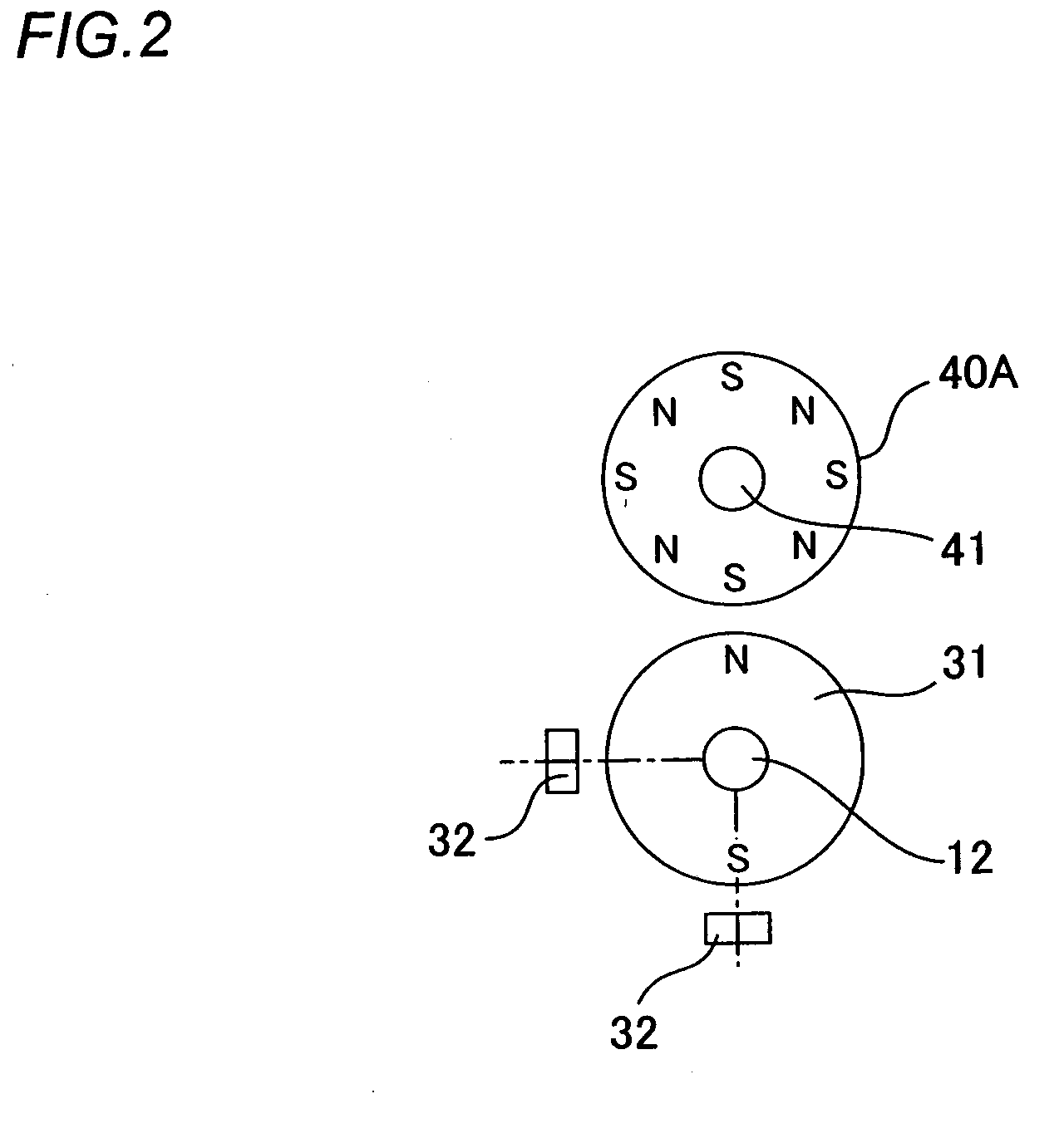
[0023]FIG. 1A is a schematic configuration diagram showing the geared motor of the present example, and FIG. 1B is a partial structural diagram of the same. A geared motor 10 comprises a motor body 11 and a reduction gear 13 connected to a motor shaft 12 of the motor body 11. A gear shaft 14 that is an output shaft of the reduction gear 13 is connected to a load side machine device 15. The machine device 15 is positioned and controlled within a prescribed operating range by the geared motor 10.

[0024]In the present embodiment, the operating range of the machine device 15 corresponds to the multiple rotations of the gear shaft 14; e.g., the operating range of the machine device 15 corresponds to two rotations (720°) of the gear shaft 14. The reduction r...


PUM


Abstract

A multiple-rotation absolute-value encoder of a geared motor, wherein the geared motor (10) reduces the rotational speed of a motor shaft (12) and takes it out from a gear shaft (14) to drive a machine device (15) in an operating range corresponding to the two rotations of the gear shaft (14). The multiple-rotation absolute-value encoder (20) fitted to the geared motor (10) comprises a gear shaft absolute value encoder (30) detecting the absolute position of the gear shaft (14) and a load side absolute value encoder (50) having a two-pole magnet (51) and a magnetic sensor (52) rotating at a rotational speed reduced to half the rotational speed of the gear shaft (14) through the magnetic gear (40). Since the operating range of the machine device (15) corresponds to one rotation of the two-pole magnet (51), the absolute position of the machine device (15) is determined based on an output from the magnetic sensor (52). As a result, the original position of the machine device (15) can be established without requiring an additional rotating operation when the operation of the machine device is started.

Description

TECHNICAL FIELD[0001]The present invention relates to a multiple-rotation absolute-value encoder of a geared motor suitable for use in a case where the operating range of a load side device driven by the geared motor corresponds to multiple rotations of the gear shaft.BACKGROUND ART[0002]As shown in FIG. 3, the geared motor comprises a motor 1, and a reduction gear 3 connected to a motor shaft 2. A machine device 5 is driven by a gear shaft 4 of the reduction gear 3. In order to control the positioning of the machine device 5 to be within a previously determined operating range, a motor driver 6 drives and controls the motor 1 on the basis of the rotational position data of the motor obtained from a motor shaft encoder 7 via a signal processing circuit 8, and on the basis of a starting point signal obtained from a starting point sensor 9 that detects a machine starting point, which serves as an operation reference of the machine device 5.[0003]When the geared motor 1 is used to perf...

Claims


Application Information

Patent Timeline
Patent Type & Authority Applications(United States)
IPC IPC(8): G01B7/30H02K11/00
CPCG01D5/145G01D5/2451G01D2205/26G01D2205/80
Inventor MIYASHITA, KUNIOKOYAMA, JUNJIMITAMURA, MUNEOSAWAMURA, YASUO
Owner HARMONIC DRIVE SYST IND CO LTD
Why Eureka
Try Eureka