Phase controller apparatus and pulse pattern generator and error detector using the phase controller apparatus

a phase controller and phase controller technology, applied in pulse technique, phase-modulated carrier system, baseband system details, etc., can solve the problems of difficult to cope with errors, the delay device of the trombone shape is not easy to upsize and respond to, and the phase delay of the signal obtained is not easy to achieve. the effect of high accuracy

Inactive Publication Date: 2009-06-04
ANRITSU CORP
View PDF2 Cites 14 Cited by
  • Summary
  • Abstract
  • Description
  • Claims
  • Application Information

AI Technical Summary

Benefits of technology

[0173]In this way, in the phase controller apparatus according to the invention, the first signal input to the quadrature modulator and the second signal output from the quadrature modulator are input into the phase comparison unit, and the direct current voltage input to the quadrature modulator is controlled in a variable way to make an output value of the phase comparison unit be the value corresponding to the desired phase delay, hence to obtain the second signal having the desired delay with respect to the first signal to be phase-controlled, without effect of the quadrature error in the quadrature modulator.
[0174]Further, the pulse pattern generator and the error detector according to the invention use the phase controller apparatus, as mentioned above, in which the first signal input to the quadrature modulator and the second signal output from the quadrature modulator are input into the phase comparison unit and the direct current voltage input to the quadrature modulator is controlled in a variable way to make the output value of the phase comparison unit be the value corresponding to the desired phase delay, hence to obtain the second signal having the desired delay with respect to the first signal to be phase-controlled, without effect of the quadrature error in the quadrature modulator.
[0175]Therefore, it is possible to realize the pulse pattern generator and the error detector having a high accuracy.

Problems solved by technology

The trombone-shaped delay device, however, has problems of upsizing and response speed.
When there is an offset error independent of the direct current voltages Vi and Vq in the quadrature modulator, an error occurs in the phase delay of the signal obtained by applying the direct current voltages Vi and Vq.
Since each error of the quadrature modulator shows frequency dependence, it is very difficult to cope with the error according to the technique disclosed in the US2004 / 0250192A1 when the frequency of the signal to be controlled varies in a wide range as described above.
Therefore, when realizing the pulse pattern generator and the error detector using the quadrature modulator as the phase controller apparatus, it is very difficult to realize them with a high accuracy, respectively.

Method used


Image

  • Phase controller apparatus and pulse pattern generator and error detector using the phase controller apparatus
  • Phase controller apparatus and pulse pattern generator and error detector using the phase controller apparatus
  • Phase controller apparatus and pulse pattern generator and error detector using the phase controller apparatus

Examples


first embodiment

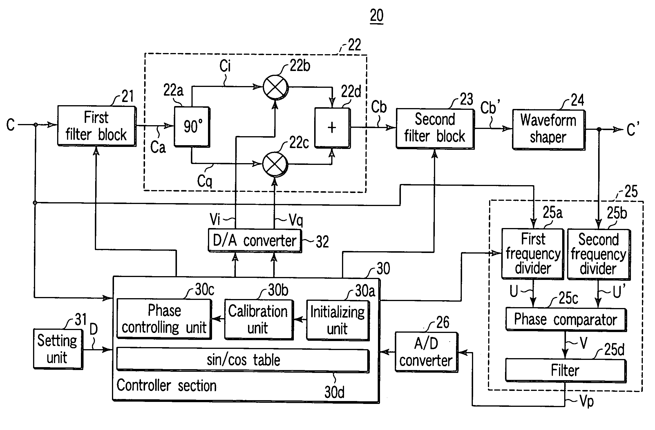
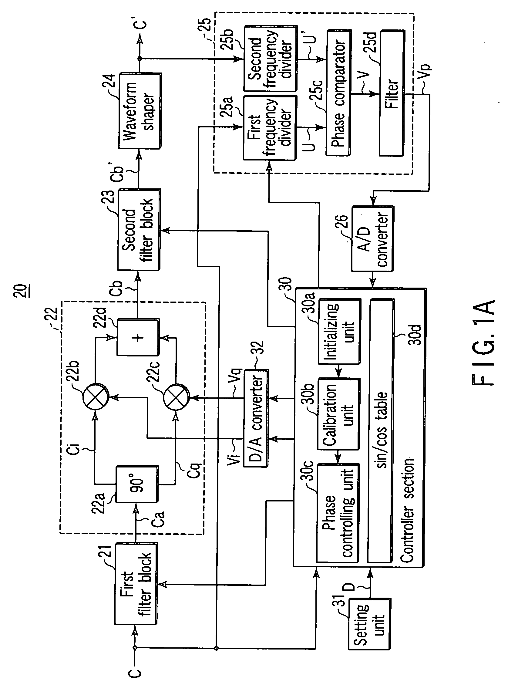
[0201]FIG. 1A is a block diagram showing the structure when a phase controller apparatus 20 according to the invention controls a phase of a rectangular wave signal as a first embodiment.

[0202]The phase controller apparatus 20 according to the first embodiment shown in FIG. 1A basically comprises: a quadrature modulator 22 which divides a first signal C input as a local signal into an I channel signal Ci and a Q channel signal Cq orthogonal to each other and outputs a second signal C′ having a desired phase delay D corresponding to direct current voltages Vi and Vq as for the first signal C by giving the direct current voltages Vi and Vq to the I channel signal Ci and the Q channel signal Cq respectively; a phase comparison unit 25 which detects a phase difference θ between the first signal C input to the quadrature modulator 22 and the second signal C′ output from the quadrature modulator 22; a setting unit 31 for setting the desired phase delay D; and a controller section 30 which...

second embodiment

[0278]FIG. 10A is a block diagram showing the structure when a phase controller apparatus 20′ according to a second embodiment of the invention controls the phase of a sine wave signal.

[0279]In FIG. 10A, the same reference numerals as those of FIG. 1A are attached to the same components as the phase controller apparatus 20 according to the first embodiment and their description is omitted.

[0280]The first embodiment is about the phase controller apparatus 20 which gives the phase delay to the first signal C of rectangular wave signal such as a clock signal and outputs it.

[0281]On the other hand, the phase controller apparatus 20′ according to the second embodiment shown in FIG. 10A controls the phase of the first signal C and the second signal C′ of sine wave signal.

[0282]In this case, in the phase controller apparatus 20′ shown in FIG. 10A, since the first signal C of sine wave signal is input to the phase controller apparatus 20′, the first filter block 21 and the waveform shaper 2...

third embodiment

[0287]FIG. 10C is a block diagram showing the structure of a pulse pattern generator 100 using the phase controller apparatus 20 according to the first embodiment as a third embodiment of the invention.

[0288]In FIG. 10C, the same reference numerals as those in FIG. 1A are attached to the same components as the phase controller apparatus 20 according to the first embodiment and their description is omitted.

[0289]The pulse pattern generator 100 shown in FIG. 10C basically includes: a pulse pattern generating unit 40 which generates a desired pulse pattern signal; the phase controller apparatus 20 which controls a phase difference between the desired pulse pattern signal from the pulse pattern generating unit 40 and a clock signal; and a pulse pattern output unit 46 which outputs the desired pulse pattern signal supplied from the pulse pattern generating unit 40 with a predetermined correction applied to the above signal whose phase difference with the clock signal is controlled by the...


PUM


Abstract

A quadrature modulator divides a first signal input as a local signal into an I channel signal and a Q channel signal orthogonal to each other and outputs a second signal having a desired phase delay corresponding to direct current voltages as for the first signal by giving the direct current voltages Vi and Vq to the I channel signal and the Q channel signal, respectively. A phase comparison unit detects a phase difference θ between the first signal and the second signal. A setting unit sets the desired phase delay. A controller section controls the direct current voltages supplied to the I channel signal and the Q channel signal respectively in the quadrature modulator so that an output value corresponding to the phase difference θ detected by the phase comparison unit is equal to a value corresponding to the desired phase delay set by the setting unit, and controls the direct current voltages to be the direct current voltages Vi and Vq satisfying the relation of Vi=cos θ and Vq=sin θ.

Description

TECHNICAL FIELD[0001]The present invention relates to a phase controller apparatus, and a pulse pattern generator and an error detector using the phase controller apparatus, and particularly to a phase controller apparatus which gives a desired delay by using a quadrature modulator, free from effect of error in the quadrature modulator even when a signal frequency is varied into a wide band, and the pulse pattern generator and the error detector using the phase controller apparatus.BACKGROUND ART[0002]For example, in a measurement system for data signal using a pulse pattern generator and an error detector, a phase controller apparatus which gives a desired delay to a clock signal is used.[0003]As a delay device which gives a desired delay to a signal, there has been hitherto known a trombone-shaped delay device which varies the length of a signal line mechanically, for example, as disclosed in Jpn. Pat. Appln. KOKAI Publication No. 11-163608.[0004]The trombone-shaped delay device, ...

Claims


Application Information

Patent Timeline
Patent Type & Authority Applications(United States)
IPC IPC(8): H03H11/16
CPCH04L27/364H04L27/0014H04L2027/0016H04L2027/0067H04L2027/0044H04L2027/0053H04L2027/0055H04L2027/0018
Inventor SHIRATSUCHI, SATORUFUJINUMA, KAZUHIROYAMAGUCHI, KAZUHIKO
Owner ANRITSU CORP
Why Eureka
Try Eureka