Solid-state laser device

a laser device and solid-state technology, applied in laser devices, laser details, active medium shape and construction, etc., can solve the problems of destroying the coating provided on the surface of optical components, reducing the light-condensing capability of the laser beam, and reducing the beam beam beam beam transmittance, so as to prevent the degradation of optical components and enhance the reliability of the solid-state laser device

Inactive Publication Date: 2009-06-04
MITSUBISHI ELECTRIC CORP
View PDF0 Cites 22 Cited by
  • Summary
  • Abstract
  • Description
  • Claims
  • Application Information

AI Technical Summary

Benefits of technology

[0013]According to the present invention, as explained above, it is possible to always maintain the surrounding atmosphere of an optical system that transmits or shuts a laser beam in a clean state; therefore, without installing the device in an environment such as a clean ro...

Problems solved by technology

As for a solid-state laser device, optical components mounted in a light path thereof are contaminated by ingress of dust from outside of the light path, so that the transmissivity of a laser beam is reduced, which has caused a problem.
In addition, dust that adheres onto surfaces of the optical components scatters a laser beam that passes through the optical compone...

Method used


Image

  • Solid-state laser device
  • Solid-state laser device
  • Solid-state laser device

Examples


embodiment 1

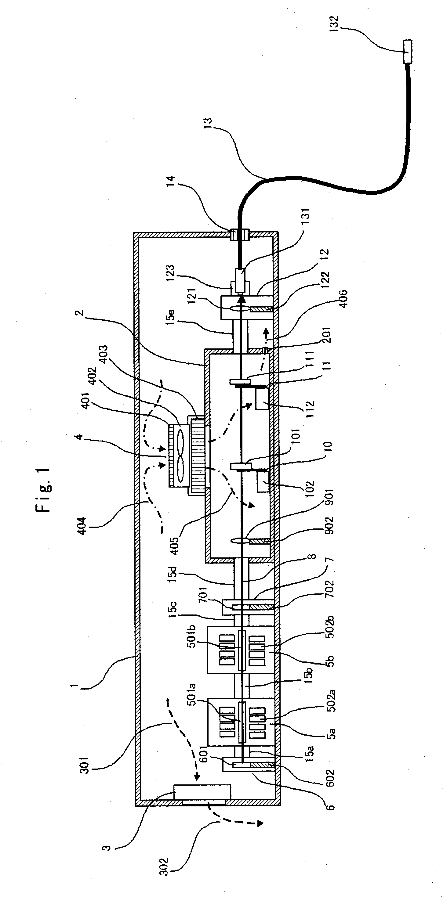
[0018]FIG. 1 is a schematic diagram illustrating a configuration of a solid-state laser device in Embodiment 1 of the present invention. In FIG. 1, “1” designates an outer casing that has an approximately sealed structure, which also serves as a protection enclosure so as to prevent leakage of a laser beam and scattered light to the exterior. Here, the approximately sealed structure means that, according to the International Protection code of foreign-substance ingress specified based on IEC International Standard 529, the structure has the sealing property in IP 21 through IP 56 or that equivalent to these IP codes (hereinafter in a similar fashion). “2” designates an inner casing that is disposed in the interior of or inside the outer casing 1. “3” designates a dehumidifier that is a dehumidifying means mounted on a side wall of the outer casing 1 so that water moisture within the outer casing 1 is released outside the outer casing 1. “301” and “302” are the broken lines that sche...

embodiment 2

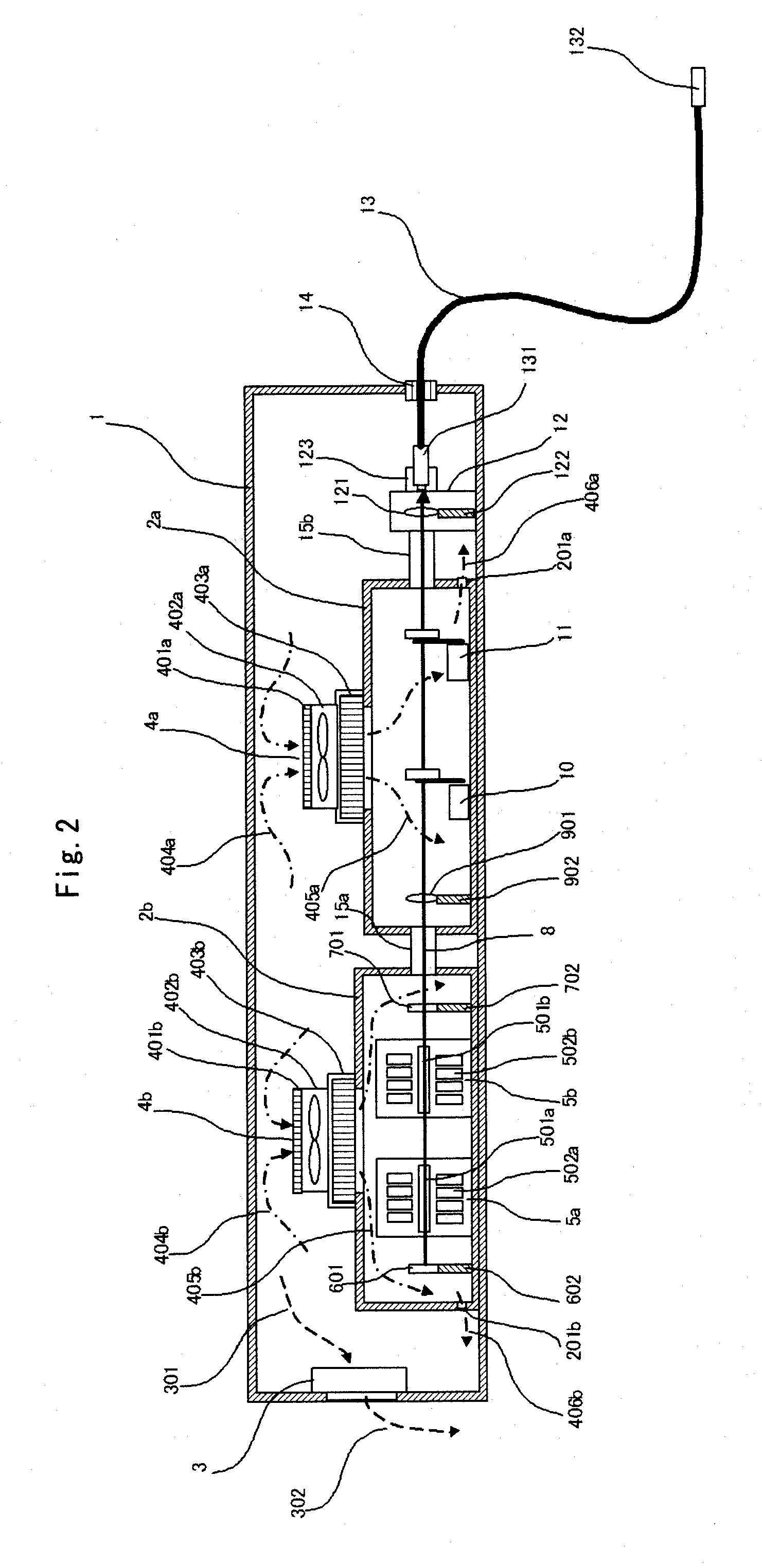
[0026]FIG. 2 is a schematic diagram illustrating a configuration of a solid-state laser device in Embodiment 2 of the present invention. In this embodiment, two of such inner casings 2a and 2b are provided inside a single such outer casing 1 having an approximately sealed structure. Inside the first inner casing 2a, in the same manner as Embodiment 1, the collimation lens 901, the process shutter unit 10, and the safety shutter unit 11 are disposed. In addition, inside the second inner casing 2b, there disposed is a laser light-source that is constituted of two of such cavity units 5a and 5b, the totally reflecting mirror 601, and the partially reflecting mirror 701.

[0027]As described in this embodiment, even when a configuration is adopted in which a plurality of such inner casings 2a and 2b are provided inside the single outer casing 1, it is not only possible to obtain effects similar to Embodiment 1, but also possible, by disposing the cavity units 5a and 5b inside the inner cas...

embodiment 3

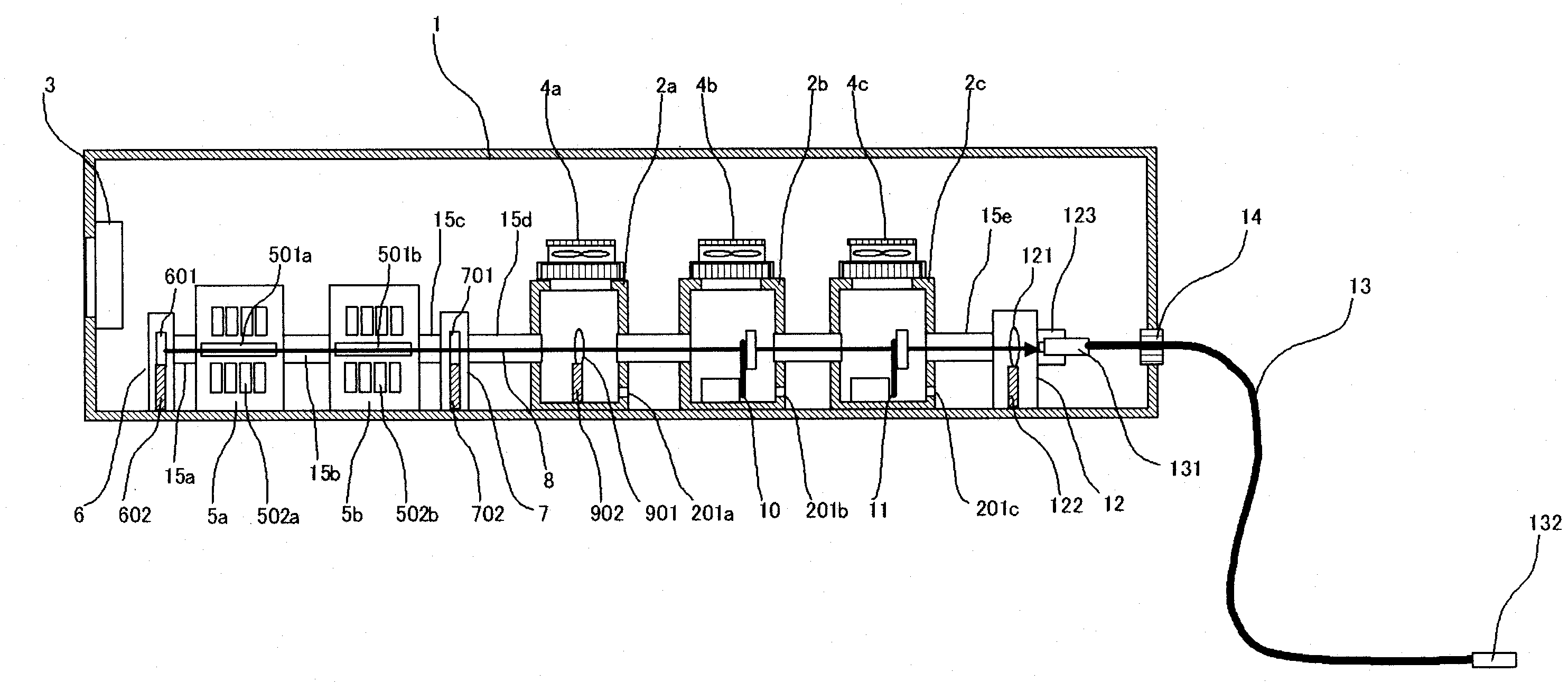
[0031]FIG. 3 is a schematic diagram illustrating a configuration of a solid-state laser device in Embodiment 3 of the present invention. In this embodiment, such inner casings 2a, 2b, and 2c are individually mounted for the collimation lens 901, the process shutter unit 10, and the safety shutter unit 11, which are the units constituting part of an optical system that transmits such laser beam 8 into the optical fiber 13. According to this embodiment, it is also possible to obtain effects similar to Embodiment 1 and Embodiment 2; moreover, because the inner casings 2a, 2b, and 2c are individually provided for the units each, it is only required to open the inner casing 2 of a unit that is to be maintained when a maintenance work is carried out for each unit; therefore, it is possible to effectively reduce risks of ingress of dust or the like into each inner casing 2 for the rest of the units, and to further increase reliability.

[0032]Note that, in this embodiment, a structure is des...


PUM


Abstract

In a solid-state laser device, a single outer casing (1) having an approximately sealed structure is included; a single or a plurality of inner casings (2) are provided inside the outer casing (1); in some or all of the inner casings (2), an air cleaning unit (4) is included in which the air within the outer casing (1) is made clean and supplied into the inner casings (2); inside the outer casing (1), there disposed are a laser light-source (5, 6, 7) having a solid-state laser medium (501) and a light resonator, and an optical system (10, 11, 901) that transmits or interrupts a laser beam (8) emitted from the laser light-source; in addition, the laser light-source (5, 6, 7) and the optical system (10, 11, 901) or part of them are contained inside the inner casings (2); thus, in a simple, compact and inexpensive configuration, it is possible to prevent degradation of optical components and dew condensation thereon, and to stably supply a laser beam.

Description

TECHNICAL FIELD[0001]The present invention relates to solid-state laser devices that achieve high reliability thereof.BACKGROUND ART[0002]As for a solid-state laser device, optical components mounted in a light path thereof are contaminated by ingress of dust from outside of the light path, so that the transmissivity of a laser beam is reduced, which has caused a problem. In addition, dust that adheres onto surfaces of the optical components scatters a laser beam that passes through the optical components, so that a light-condensing capability of the laser beam is reduced, which has caused a problem. In addition, adhered substance on the surfaces of the optical components absorbs a laser beam, resulting in not only destroying coating provided on the surfaces of the optical components, but also damaging host material of the optical components, which has caused a problem.[0003]To this end, in a conventional solid-state laser machining apparatus, the above problems have been solved in ...

Claims


Application Information

Patent Timeline
IPC IPC(8): H01S3/11H01S3/00H01S3/10
CPCH01S3/005H01S3/0092H01S3/025H01S3/117H01S3/07H01S3/0941H01S3/027
Inventor FUJIKAWA, SHUICHIKANO, JUNJIKUBA, KAZUKI
Owner MITSUBISHI ELECTRIC CORP
Why Eureka
Try Eureka