
Film formation method, cleaning method and film formation apparatus

Inactive Publication Date: 2009-06-04
TOKYO ELECTRON LTD
View PDF12 Cites 19 Cited by
  • Summary
  • Abstract
  • Description
  • Claims
  • Application Information

AI Technical Summary

Benefits of technology

[0008]In view of the above, the present invention provides a film formation, a cleaning method and a film formation apparatus which are capable of completely cleaning a cleaning target portion without inflicting damages on a chamber wall and the like when a metal film or a metal compound film is formed by using, as a processing gas, a metal chloride compound gas such as TiCl4 or the like.
[0031]In accordance with the present invention, Cl2 gas that is less active than conventionally used ClF3 gas but is highly reactive with a material adhered in the chamber is used as a cleaning gas, and the cleaning is performed by independently controlling the temperature of each of the substrate mounting table, the gas ejection member and the wall portion of the chamber so that the temperature of the cleaning target portion is not lower than the decomposition start temperature of Cl2 gas and the temperature of the non-cleaning target portion is not higher than the decomposition start temperature. As a consequence, the cleaning target portion can be reliably cleaned without inflicting damages on the chamber wall and the like.

Problems solved by technology

For that reason, a cleaning temperature needs to be decreased to about 200° C. Accordingly, a period of time to increase or decrease the temperature in the chamber is required between the film formation and the cleaning, thus severely deteriorating the productivity of the semiconductor apparatus manufacturing process.
Further, it is unrealistic to completely remove the by-products, or damages are inflicted on the chamber wall or in-chamber members.
Besides, regardless of the existence of the above Patent Document, the cleaning process using a chlorine-based gas such as Cl2 gas or the like has not been practically employed.

Method used


Image

  • Film formation method, cleaning method and film formation apparatus
  • Film formation method, cleaning method and film formation apparatus
  • Film formation method, cleaning method and film formation apparatus

Examples


Embodiment Construction

[0046]The embodiments of the present invention will be described with reference to the accompanying drawings.

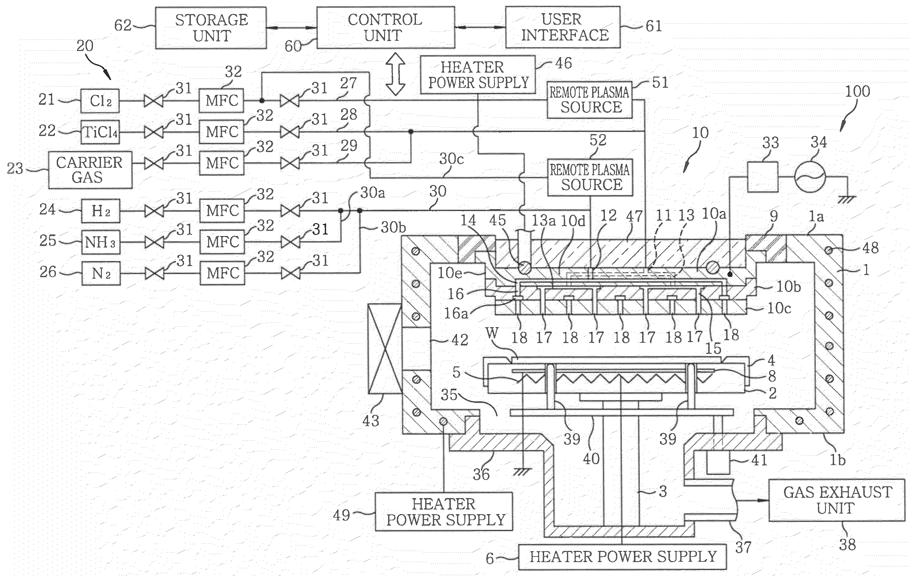
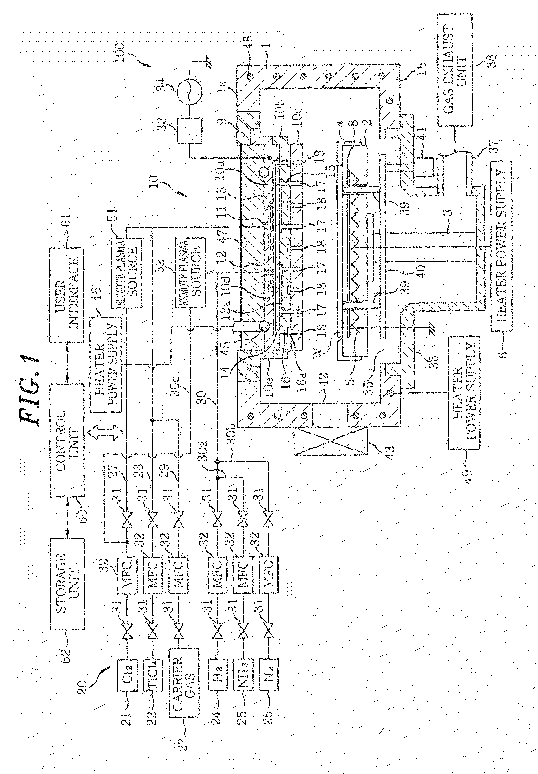
[0047]FIG. 1 shows a schematic cross sectional view of an example of a film formation apparatus used for implementing a Ti-based film forming method in accordance with an embodiment of the present invention. A TiN film formation apparatus and a Ti film formation apparatus have similar configuration. Therefore, the film formation apparatus employed herein is applicable to the TiN film formation and the Ti film formation.

[0048]A Ti film formation apparatus 100 includes a substantially cylindrical chamber 1. The chamber 1 is made of, e.g., aluminum or aluminum alloy (e.g., JIS A5052). In the chamber 1, a susceptor (stage) 2 for horizontally supporting a wafer W as a target substrate is disposed while being supported by a cylindrical supporting member 3 provided at a center of a lower portion thereof. The susceptor 2 is made of ceramics, e.g., AlN or the like, and a heater 5 is e...


PUM

PropertyMeasurementUnit
Temperatureaaaaaaaaaa

Abstract

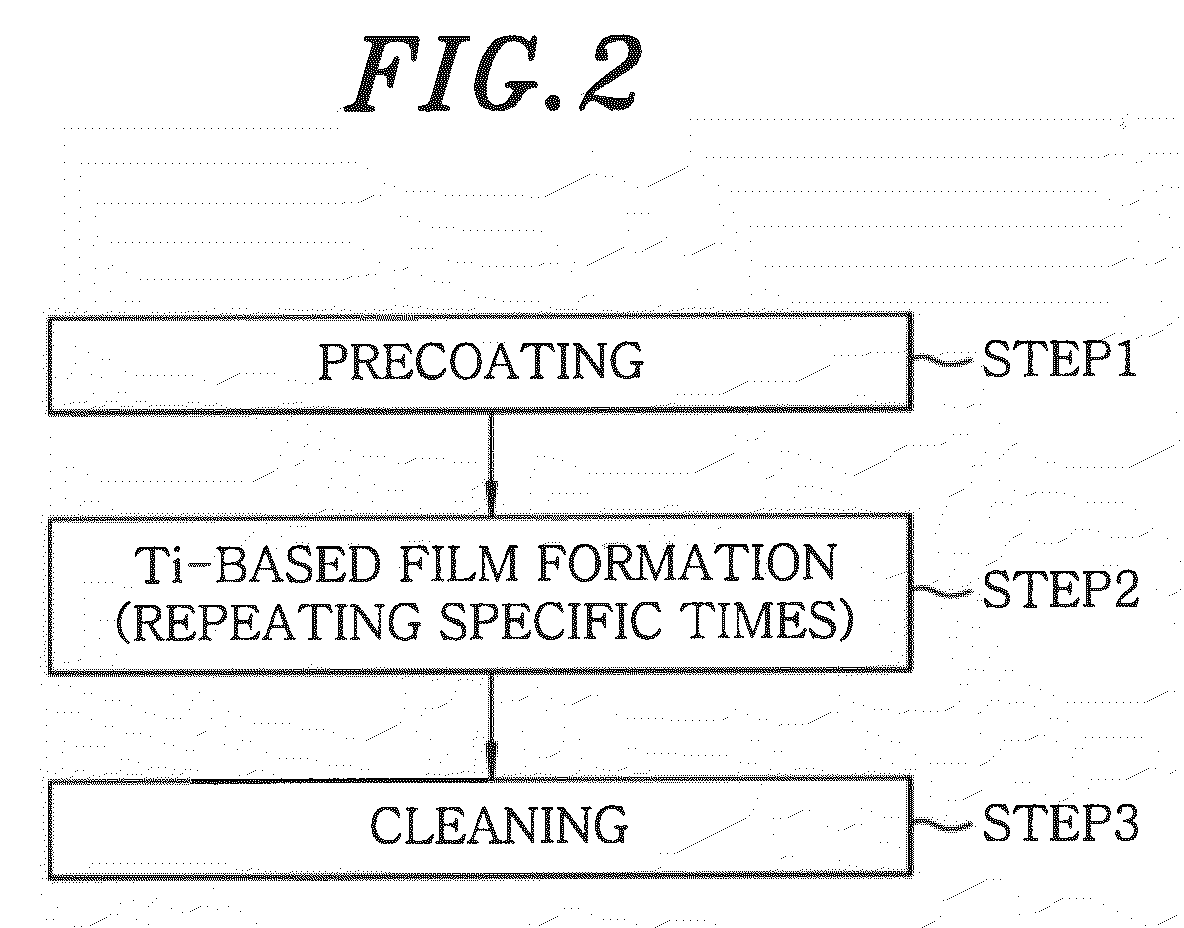
A treatment gas is supplied to form a Ti-based film on a predetermined number of wafers W while setting a temperature of a susceptor 2 in a chamber 1 to a predetermined temperature. After this, the interior of the chamber 1 containing no wafers W is cleaned by discharging Cl2 gas as a cleaning gas from a shower head 10 into the chamber 1. During this cleaning, the temperature of each of the susceptor 2, the shower head 10, and the wall portion of the chamber 1 is independently controlled so that the temperature of the susceptor 2 is not lower than the decomposition start temperature of Cl2 gas and the temperature of the shower head 10 and the wall portion of the chamber 1 is not higher than the decomposition start temperature.

Description

[0001]This application is a Continuation application of PCT International Application No. PCT / JP2007 / 063754 filed on 10 Jul. 2007, which designated the United States.FIELD OF THE INVENTION[0002]The present invention relates to a film formation method for forming a metal film or a metal compound film on a surface of a target substrate provided in a chamber by discharging a processing gas containing a metal chloride compound gas such as TiCl4 gas or the like from a shower head into the chamber, a method for cleaning an interior of a chamber where the film forming method is carried out, and a film formation apparatus.BACKGROUND OF THE INVENTION[0003]In a manufacturing process of a semiconductor apparatus, various gas processes such as a film forming process, an etching process and the like are performed on a semiconductor wafer as a target substrate (hereinafter, referred to as a “wafer”). These gas processes are carried out by supplying a reactant gas (corrosion gas), e.g., a processi...

Claims


Application Information

Patent Timeline
IPC IPC(8): C23C16/513C23C16/44B05C11/00B08B5/00B08B6/00
CPCC23C16/4405C23C16/08C23C16/52
Inventor MURAKAMI, SEISHIKOIZUMI, MASAKIASHIZAWA, HIROAKIKOIZUMI, MASATO
Owner TOKYO ELECTRON LTD
Learn More