
Image forming method, toner and image forming apparatus

Inactive Publication Date: 2009-06-04
RICOH KK
View PDF9 Cites 13 Cited by
  • Summary
  • Abstract
  • Description
  • Claims
  • Application Information

AI Technical Summary

Benefits of technology

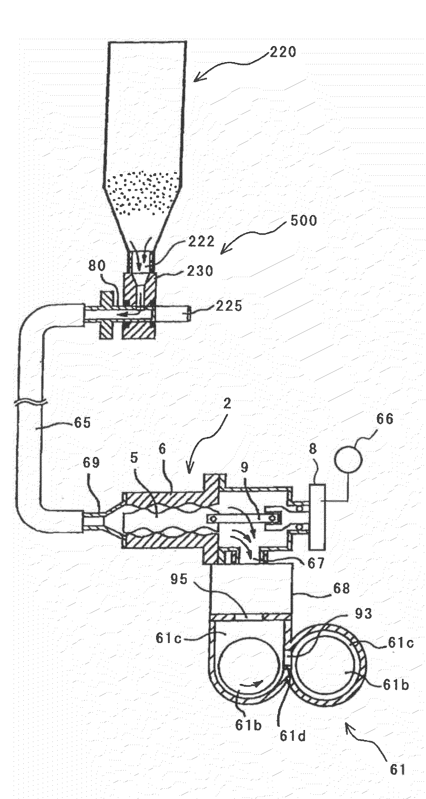
[0013]Designed in light of the present situation described above, the present invention is aimed at solving problems in related art and achieving the following object. An object of the present invention is to provide an image forming method which includes forming an image by supplying a toner to a developing device with the use of a screw pump, and which is capable of preventing the occurrence of image defect that stems from formation of toner aggregates inside a screw pump and also preventing the occurrence of trouble that stems from excessive addition of small particle size silica; a toner used in the image formation; and an image forming apparatus using the toner.
[0031]As a result of experiments performed by the present inventors, which are to be later explained with reference to Tables 1 and 2 and FIG. 6, the following has been found: in the case where A and B satisfy the expression −18A+17.92≦B≦−34A+33.96 (A denotes the average degree of circularity of a toner, and B, expressed as percent by mass, denotes the amount of small particle size silica relative to the mass of toner base particles) when an image is formed by supplying a toner to a developing device with the use of a screw pump, it is possible to prevent the occurrence of cleaning defect and a rise in bulk density caused by excessive addition of small particle size silica and also to prevent the occurrence of fireflies caused by formation of toner aggregates.
[0032]The present invention offers a superior effect of preventing the occurrence of image defect that stems from formation of toner aggregates inside a screw pump and also preventing the occurrence of trouble that stems from excessive addition of small particle size silica.

Problems solved by technology

The cohesion of these aggregates is weak to such an extent that they crumble when touched by fingertips; thus, some of the aggregates are broken into fine pieces through agitation by an agitating member inside the developer housing section and come back into the state of ordinary toner powder even if supplied to the developing device along with other toner.
When these aggregates are transferred from the photoconductor to a recording medium such as transfer paper by a transfer device, image defect is caused.
Meanwhile, in the case of a linear image, the part where the aggregates have been attached blackens, and thus thin lines may be unable to be reproduced.
However, when the small particle size silica is excessively added, the following troubles arise in some cases.
When the small particle size silica is added in larger amounts than necessary to toner base particles having a high degree of circularity, such a trouble is caused that there is a tremendous increase in fluidity and thus an excessive increase in the bulk density of the toner.
In the foregoing device, when the bulk density of the developer is excessively high, the toner concentration is most suitable, but the sensor is likely to judge that the concentration of developer components other than the toner is higher than the toner concentration, and so the toner may be excessively supplied, thereby possibly leading to an extremely high toner concentration as a result.
Moreover, in the case where a cleaning device for removing toner on the surface of a toner image bearing member such as a photoconductor removes the toner by means of a blade, the blade is often partially abraded if a high proportion of small particle size silica is contained in the toner to be removed.
When the blade of the cleaning device is partially abraded, such a cleaning defect is caused in which toner remains in the form of a streak on a part of the toner image bearing member surface facing the abraded part of the blade, and this cleaning defect leads to an image defect in which a black streak appears in an image formed on a recording medium.

Method used


Image

  • Image forming method, toner and image forming apparatus
  • Image forming method, toner and image forming apparatus
  • Image forming method, toner and image forming apparatus

Examples


example 1

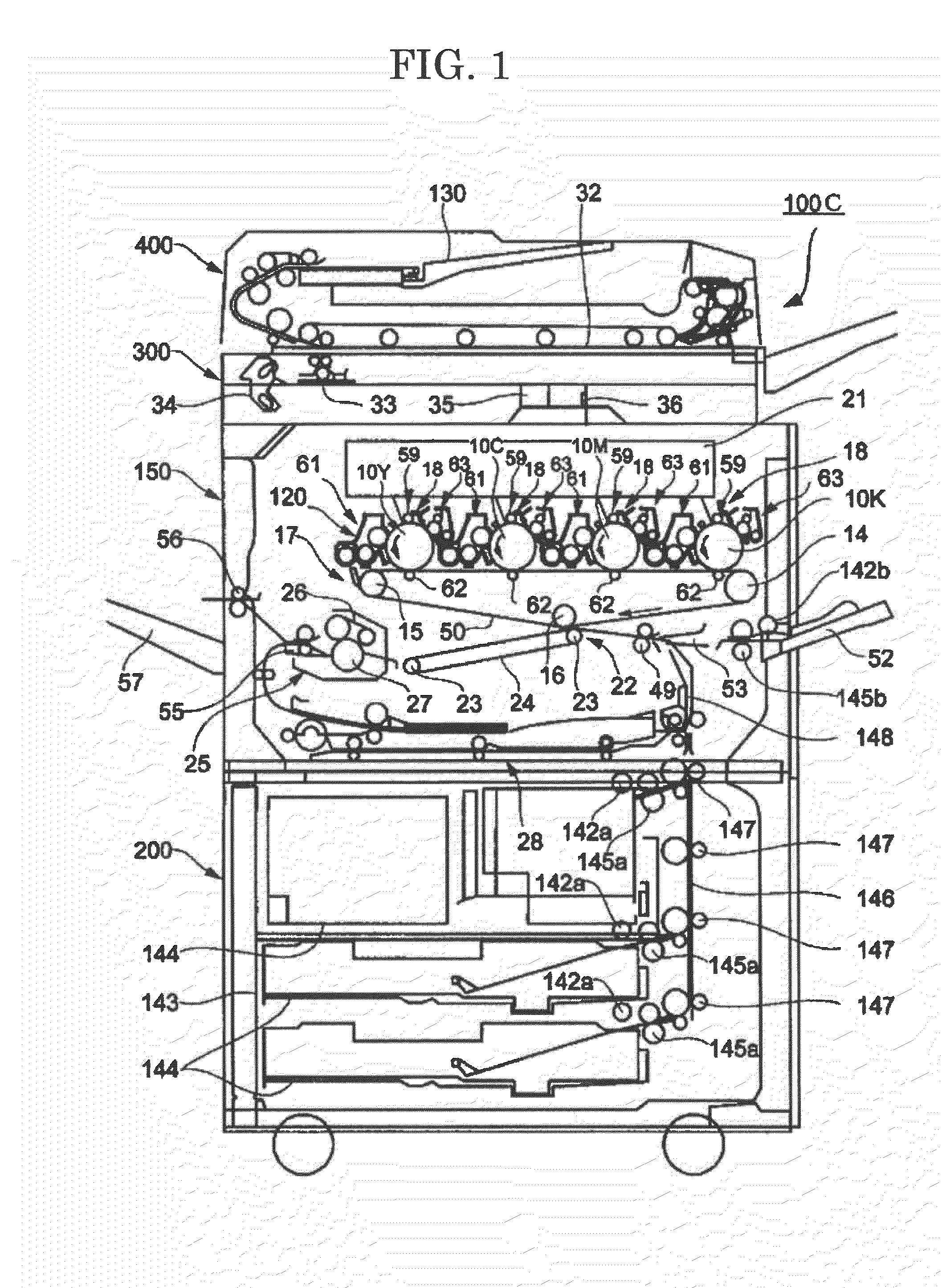
[0196]First of all, a method for producing a toner used in a first example (hereinafter referred to as “Example 1”) of the copier 100C is described.

[0197]Into a reactor equipped with a cooling tube, an agitator and a nitrogen-introducing tube, 229 parts by mass of an ethylene oxide (2 mol) adduct of bisphenol A, 529 parts by mass of a propion oxide (3 mol) adduct of bisphenol A, 208 parts by mass of terephthalic acid, 46 parts by mass of adipic acid and 2 parts by mass of dibutyltin oxide were poured, and these ingredients were subjected to reaction at 230° C. under normal pressure for 8 hr. Next, the ingredients were subjected to reaction under a reduced pressure of 10 mmHg to 15 mmHg for 5 hr, then at 180° C. under normal pressure for 2 hr with the addition of 44 parts by mass of trimellitic anhydride into the reactor, and an unmodified polyester resin (1) was thus synthesized.

[0198]The unmodified polyester resin obtained had a number average molecular weight of 2,500, a weight av...

example 2

[0245]In a second example (hereinafter referred to as “Example 2”) of the copier 100C, a toner was produced similarly to that in Example 1, except that the amount of the modified layered inorganic mineral (product name: CLAYTONE APA) was changed from 1.7 parts by mass to 1.3 parts by mass and the amount of the small particle size silica was changed from 1.5 parts by mass to 1.0 part by mass.

example 3

[0246]In a third example (hereinafter referred to as “Example 3”) of the copier 100C, a toner was produced similarly to that in Example 1, except that the amount of the modified layered inorganic mineral (product name: CLAYTONE APA) was changed from 1.7 parts by mass to 1.0 part by mass and the amount of the small particle size silica was changed from 1.5 parts by mass to 0.5 parts by mass.


PUM

PropertyMeasurementUnit
Temperatureaaaaaaaaaa
Lengthaaaaaaaaaa
Lengthaaaaaaaaaa

Abstract

To provide an image forming method including conveying a toner by means of a toner supply device that supplies the toner from inside a toner housing container into a developer housing section of a developing device with the use of a screw pump, and forming an image on a recording medium by developing a latent image on a latent image bearing member to form a toner image with the use of a developer and by transferring the toner image to the recording medium by means of a transfer device, wherein the toner is formed by adding small particle size silica to toner base particles, and wherein when A represents the average degree of circularity of the toner, and B, expressed as percent by mass, represents the amount of the small particle size silica relative to the mass of the toner base particles, the expression −18A+17.92≦B≦−34A+33.96 is satisfied.

Description

BACKGROUND OF THE INVENTION[0001]1. Field of the Invention[0002]The present invention relates to an image forming method used in an image forming apparatus such as a copier, a facsimile, a printer, etc.; a toner used in an image forming apparatus; and an image forming apparatus using the toner.[0003]2. Description of the Related Art[0004]As a toner supply device that supplies toner in a toner storage container to a developer housing section of a developing device in an image forming apparatus, there has conventionally been a toner supply device in which toner is conveyed using a screw pump, as described in Japanese Patent (JP-B) No. 3872506 or Japanese Patent Application Laid-Open (JP-A) No. 2007-079504. Such a toner supply device is equipped with a conveyance path member through which toner passes, and a screw pump; toner in the toner storage container is conveyed to the developer housing section by the suction of the screw pump.[0005]The screw pump is provided with a stator which ...

Claims


Application Information

Patent Timeline
IPC IPC(8): G03G9/087G03G13/16G03G15/08G03G21/18
CPCG03G9/0819G03G9/0827G03G9/08755G03G9/08793G03G15/0877G03G9/09716G03G9/09725G03G9/09783G03G15/0879G03G9/09708
Inventor KOJIMA, SATOSHISAWADA, TOYOSHINAGATOMO, TSUNEYASU
Owner RICOH KK
Learn More