
Single-layered arch support insole to be inserted into shoe

a single-layer, arch support technology, applied in the direction of insoles, uppers, bootlegs, etc., can solve the problems of manufacturing costs, increasing the number of manufacturing processes, and unable to adequately support the arch of the wearer's foot, so as to minimize fatigue on walking, prevent deformation and buckling, and even distribution of wearer's weigh

Inactive Publication Date: 2009-06-11
UMI SYST
View PDF9 Cites 17 Cited by
  • Summary
  • Abstract
  • Description
  • Claims
  • Application Information

AI Technical Summary

Benefits of technology

"The present invention provides an arch support insole that solves problems of existing insoles by improving wearing feeling, reducing fatigue on walking, and maintaining the arch support part. The insole is made of a single layer through dual injection, which minimizes the thickness of the insole and reduces manufacturing costs. The insole includes an arch support part curvedly projecting upward to support the arch of the wearer's foot and a heel support part coupled to a rear part of the insole body. The insole also includes an anti-slip part to improve grip on the shoe. The invention provides an arch support insole that improves wearing feeling, reduces fatigue on walking, and maintains the arch support part while minimizing the number of manufacturing processes and cost."

Problems solved by technology

In addition, addition of unnecessary processes upon manufacturing increases the number of manufacturing processes and manufacturing cost.
Further, the insole formed of a single material having no resilience to support the pressure periodically receives shock applied from the ground to the heel to give fatigue on walking for a long time.
Furthermore, long-term use of the insole causes deformation of the arch support part to make it impossible to sufficiently support the arch of the wearer's foot.

Method used


Image

  • Single-layered arch support insole to be inserted into shoe
  • Single-layered arch support insole to be inserted into shoe
  • Single-layered arch support insole to be inserted into shoe

Examples


first embodiment

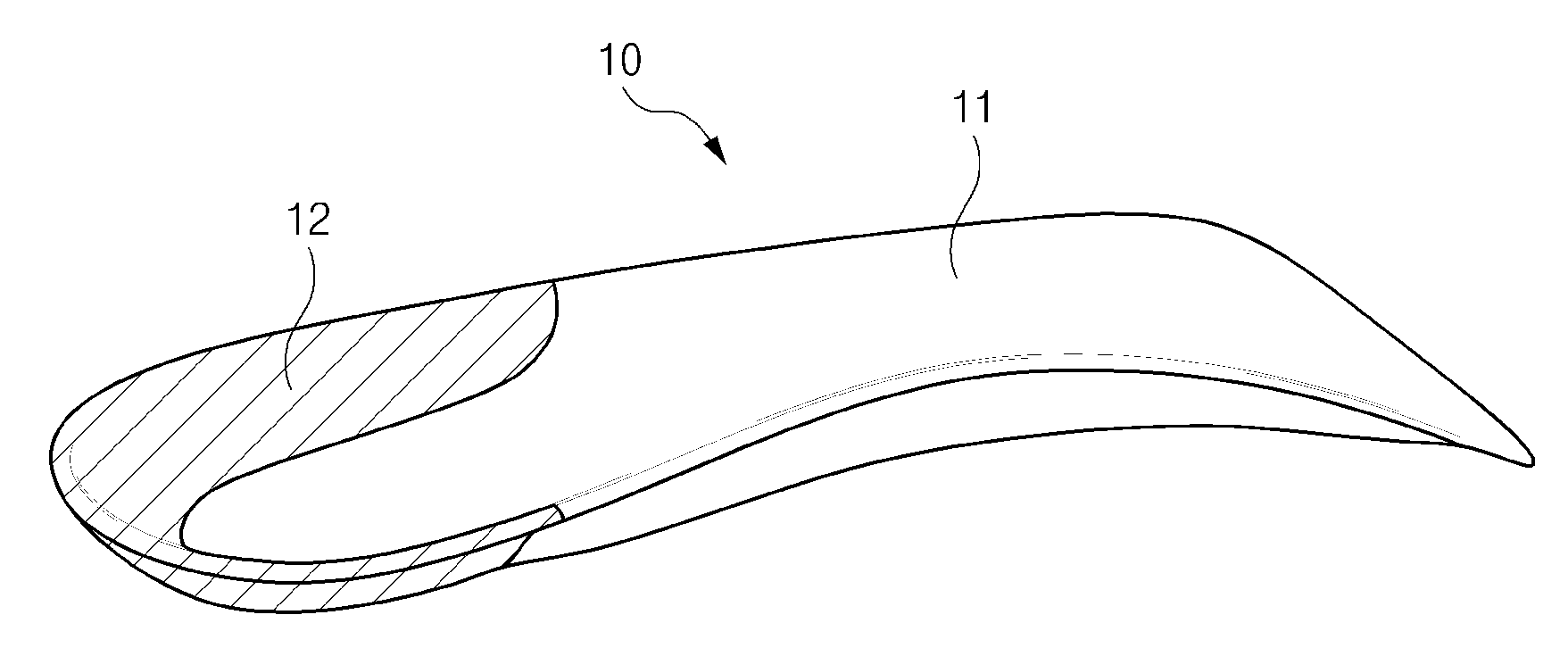
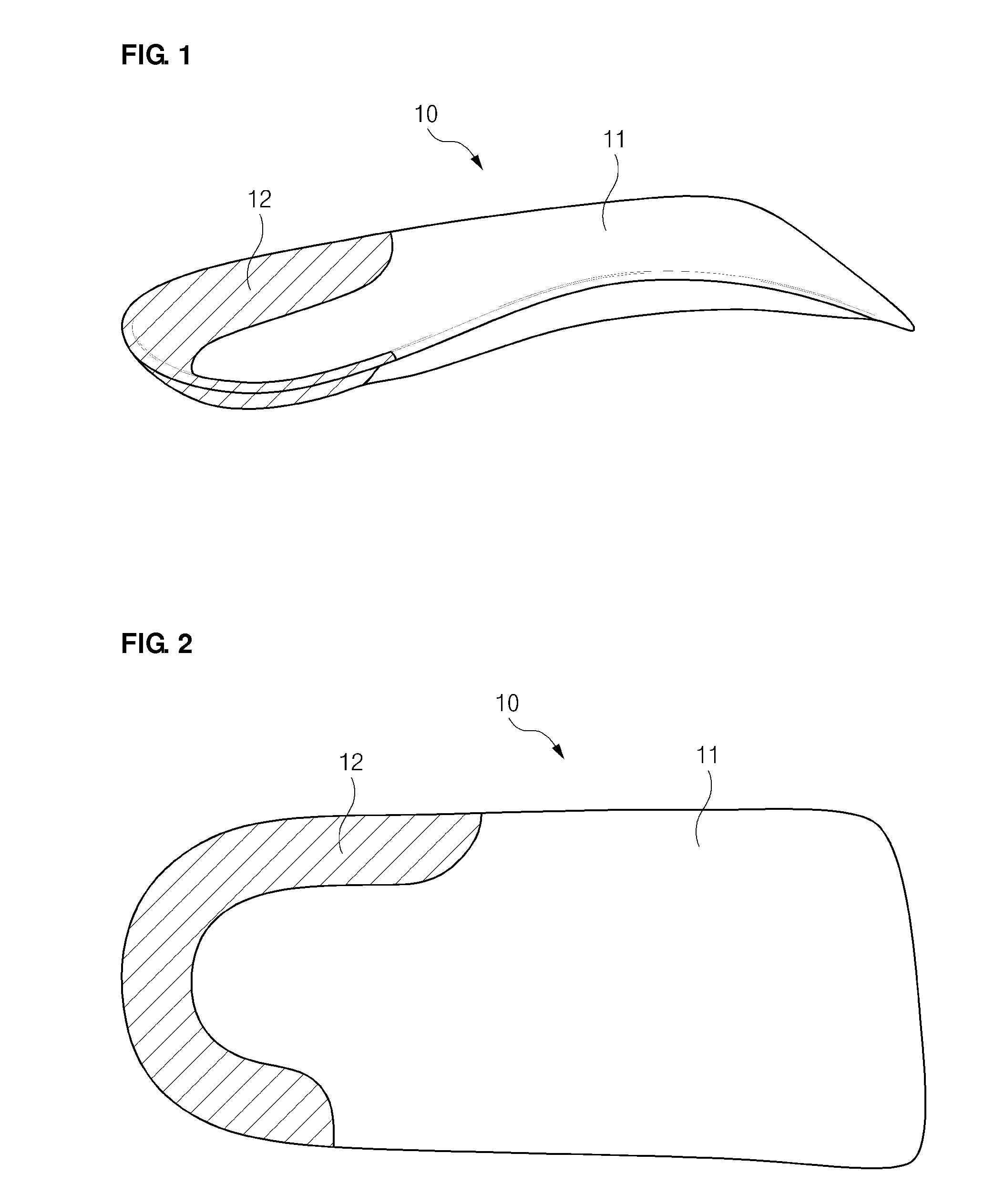
[0046]FIG. 1 is a perspective view of an insole in accordance with the first embodiment of the present invention, and FIG. 2 is a plan view of the in accordance with the first embodiment of the present invention.

[0047]The insole 10 in accordance with the first embodiment of the present invention includes an insole main body 11 corresponding to the shape of sole of a foot, except toes, and a heel support part 12 surrounding the heel of the foot. The insole main body 11 and the heel support part 12 is formed of a single layer and fabricated by plastic materials having different hardness.

[0048]In general, the insole formed of a plastic material such as polypropylene or nylon is manufactured by a plastic molding technology. In general, plastic molding methods are classified into various methods such as injection molding, press molding, transfer molding, rotary molding, thermal molding, blow molding, film blowing, extrusion, calendaring, fiber spinning, and so on. Among them, the injecti...

second embodiment

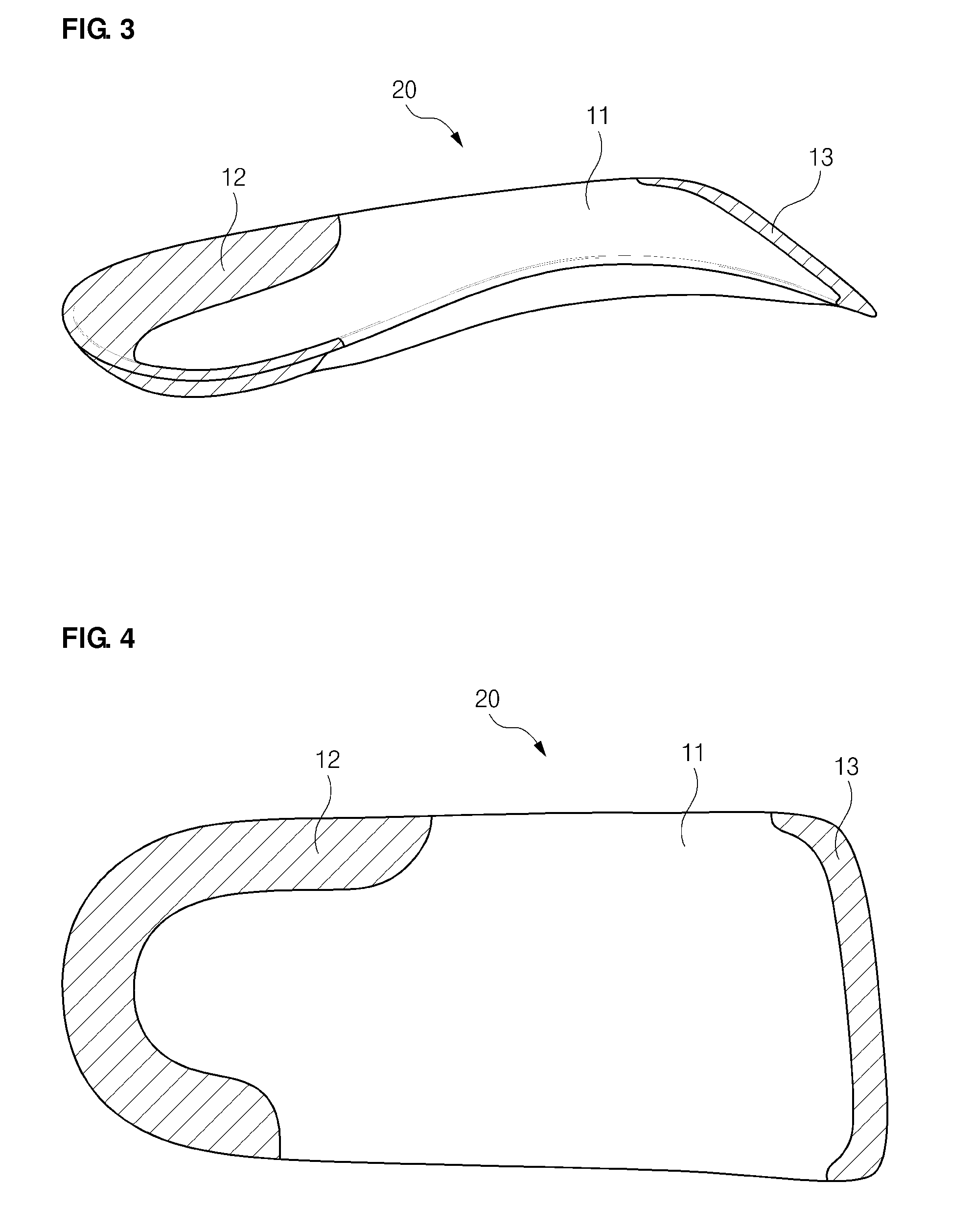
[0057]FIG. 3 is a perspective view of an insole in accordance with the second embodiment of the present invention, and FIG. 4 is a plan view of the insole in accordance with the second embodiment of the present invention.

[0058]The insole 20 in accordance with the second embodiment of the present invention further includes an anti-slip part 13 to prevent slippage of a front part of the insole 20. The heel support part 12 and the anti-slip part 13 has hardness different from the insole main body 11 such that the heel support part 12 smoothly wraps the heel and the anti-slip part 13 minimize movement of the insole 20 when the insole 20 is inserted into a shoe. The second embodiment is similar to the first embodiment, except the above description, and thus, overlapping description thereof will not be repeated.

[0059]In a manufacturing method thereof, similar to the first embodiment, a first plastic material is inserted into a first cavity to primarily form the insole main body 11, and th...

third embodiment

[0061]FIG. 5 is a perspective view of an insole in accordance with the third embodiment of the present invention, FIG. 6 is a plan view of the insole in accordance with the third embodiment of the present invention, FIG. 7 is a bottom view of the insole in accordance with the third embodiment of the present invention, and FIG. 8 is a side view of the insole in accordance with the third embodiment of the present invention. Meanwhile, in this embodiment, description overlapping the aforementioned embodiments will not be repeated.

[0062]The insole 30 in accordance with the third embodiment of the present invention, which is characterized by an arch support part different from the first and second embodiments, generally includes an insole main body 11 configured to include a portion or the entire of an arch support part curvedly projecting upward to support the arch of a wearer's foot, and a heel support part 12 coupled to a rear part of the insole main body. The insole main body 11 and ...


PUM


Abstract

Provided is an arch support insole to be inserted into a shoe. The insole should satisfy tasks for a wearer as follows: (1) improvement of wearing feeling by maximally reducing the thickness of the insole, (2) reduction of fatigue on walking by maximally preventing transmission of shocks, and (3) sufficient support of the arch of the wearer by maintaining an original shape of the arch support part. In addition, these tasks should be solved by a minimum number of manufacturing processes and minimum cost. The arch support insole includes an insole main body having a portion or the entire of an arch support part curvedly projecting upward to support the arch of a wearer's foot, and a heel support part coupled to a rear part of the insole main body, wherein the insole main body and the heel support part are formed of a single layer by dual injection, the insole main body is formed of a material having hardness higher than that of the heel support part, and a plurality of honeycomb-shaped projections are formed downward at a bottom surface of the curved arch support part.

Description

CROSS-REFERENCE TO RELATED APPLICATIONS[0001]This application claims the benefit of Korean Patent Applications No. 10-2007-0125416 and No. 10-2008-0021299 filed with the Korea Intellectual Property Office on Dec. 5, 2007 and Mar. 7, 2008, respectively, the disclosure of which is incorporated herein by reference.BACKGROUND OF THE INVENTION[0002]1. Field of the Invention[0003]The present invention relates to a single-layered arch support insole to be inserted into a shoe.[0004]2. Description of the Related Art[0005][Related Prior Art Documents][0006]1. Korean Utility Model Registration No. 20-0428449 B[0007]2. Korean Utility Model Registration No. 20-0390153 B[0008]3. Korean Utility Model Registration No. 20-0395056 B[0009]4. Korean Patent Laid-open Publication No. 2003-0093618 A[0010]5. Korean Utility Model Registration No. 20-0431315 B[0011]6. U.S. Pat. No. 6,976,322 B[0012]In general, an insole corresponds to the shape of the sole of a foot to form a curved shape such that the inso...

Claims


Application Information

Patent Timeline
Patent Type & Authority Applications(United States)
IPC IPC(8): A43B13/38
CPCA43B1/0009A43B7/141A43B17/023A43B7/143A43B7/144A43B7/142A43B17/14
Inventor KIM, HWI JIN
Owner UMI SYST
Learn More