Problem detection apparatus and method in exhaust purifying apparatus

a technology of problem detection and exhaust purification, which is applied in mechanical equipment, machines/engines, separation processes, etc., can solve problems such as non-diagnosis, and achieve the effect of increasing the reliability of the problem detection apparatus

Inactive Publication Date: 2009-06-11
MITSUBISHI FUSO TRUCK AND BUS CORPORATION
View PDF3 Cites 20 Cited by
  • Summary
  • Abstract
  • Description
  • Claims
  • Application Information

AI Technical Summary

Benefits of technology

[0026]A problem detection apparatus and method in an exhaust filtering system according to the present invention has the following effects.
[0027]A filter problem can be detected by calculating a calculation differential pressure value even in an unsteady traveling state. As a threshold value is sequentially calculated from a traveling state, a filter problem can be detected by comparing with a threshold value even in an unsteady traveling state.
[0028]A soot deposition value is calculated by considering a loss caused by Nox and heat, and a threshold value is corrected based on such a soot deposition value. Therefore, the calculated value reflects an actual driving history, and a problem can be detected by using an appropriate threshold value.
[0029]An ash deposition value is calculated by using a total fuel injection amount, and the calculated value reflects an actual driving history more than in a case of calculation based on a traveling distance.
[0030]A clogging of a filter and a leak caused by a crack can be detected. As a filter problem is checked after a lapse of certain time, the reliability of the problem detection apparatus can be increased.
[0031]FIG. 1 is a diagram showing the configuration of an engine having an embodiment of a problem detection apparatus according to the present invention;

Problems solved by technology

There are following problems in a conventional problem detection apparatus for a particulate filter.
Thus, a diagnosis is not executed.

Method used


Image

  • Problem detection apparatus and method in exhaust purifying apparatus
  • Problem detection apparatus and method in exhaust purifying apparatus
  • Problem detection apparatus and method in exhaust purifying apparatus

Examples


Embodiment Construction

[0043]Explanations will be given on an embodiment of a filter problem detection apparatus and method according to the present invention with reference to the accompanying drawings.

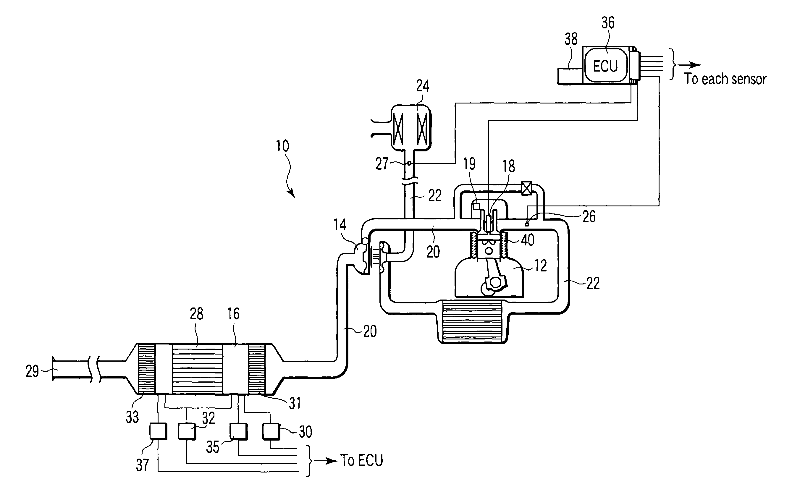
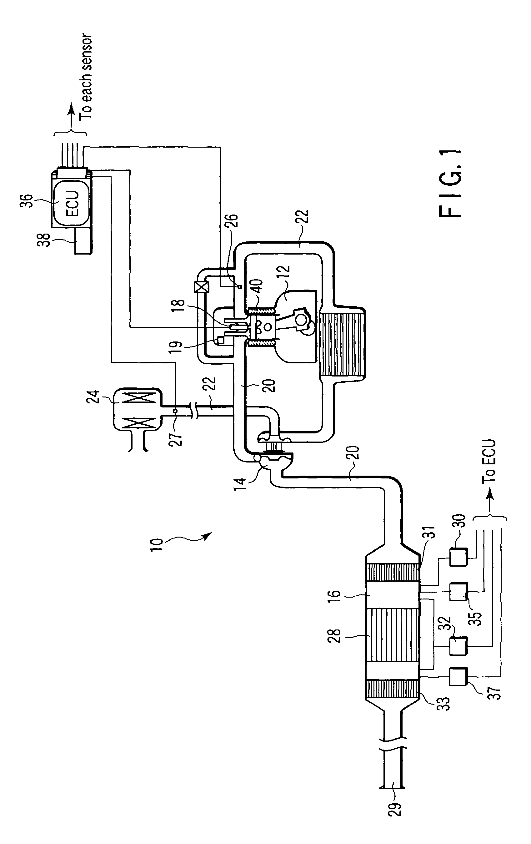
[0044]FIG. 1 shows the configuration of an engine 12 having a filter problem detection apparatus 10, as an internal combustion engine. The engine 12 is a diesel engine comprising a turbo charger 14, a DPF unit 16, a fuel supply unit 18, and an engine speed sensor 19. The turbo charger 14 is connected to an exhaust pipe 20 as an exhaust path, and a suction pipe 22 as a suction path. The turbo charger 14 pressurizes outside air suctioned through an air cleaner 24 by using an exhaust pressure, and feeds the pressurized air to the engine 12.

[0045]The suction pipe 22 is provided with a suction pressure sensor 26 to detect the pressure in the suction pipe 22, or the boost pressure by the turbo charger 14, and a suction flow rate sensor 27 to detect a flow rate in the suction pipe 22. The engine 12 is not limited...


PUM


Abstract

An exhaust purifying apparatus is provided with a filter located in an exhaust path of an internal combustion engine and configured to collect particulates in exhaust gas. The exhaust purifying apparatus is also provided with a differential pressure sensor which detects the pressure difference generated between the upstream side and downstream side of the filter. The problem detection apparatus of the exhaust purifying apparatus is provided with a differential pressure calculation unit and a judgment unit. The differential pressure calculation unit calculates the pressure difference between the upstream and downstream sides of the filter based on the operating state of the internal combustion engine. The judgment unit calculates a difference P between an actual measurement value of the pressure difference and a calculation differential pressure value compares the difference P with a threshold value, and detects that the filter has a problem.

Description

CROSS-REFERENCE TO RELATED APPLICATIONS[0001]This is a Continuation application of PCT Application No. PCT / JP2007 / 074106, filed Dec. 14, 2007, which was published under PCT Article 21 (2) in Japanese.[0002]This application is based upon and claims the benefit of priority from prior Japanese Patent Application No. 2006-350134, filed Dec. 26, 2006, the entire contents of which are incorporated herein by reference.BACKGROUND OF THE INVENTION[0003]1. Field of the Invention[0004]The present invention relates to a problem detection apparatus and method in an exhaust purifying apparatus, in an exhaust filtering system such as a DPF.[0005]2. Description of the Related Art[0006]An exhaust filtering system such as a diesel particulate filter (DPF) system has a filter inside for collecting particulates included in exhaust gas of an engine, and purifies the exhaust gas through the filter. A filter is clogged with collected particulates. Therefore, appropriate amount of the collected particulate...

Claims


Application Information

Patent Timeline
Patent Type & Authority Applications(United States)
IPC IPC(8): F01N11/00
CPCB01D53/944B01D53/9495F01N3/0231F01N9/002F01N13/0097F01N2550/04F01N2900/1406Y02T10/47F01N11/002Y02T10/40
Inventor TAKAHASHI, HIDEYUKIKOBAYASHI, TADAOOGUCHI, KOJIMOROGUCHI, YOSHIAKI
Owner MITSUBISHI FUSO TRUCK AND BUS CORPORATION
Why Eureka
Try Eureka