Valve gear and rocker ARM unit

a technology of valve gear and rocker arm, which is applied in the direction of mechanical control devices, instruments, process and machine control, etc., can solve the problems of troublesome mounting work, increased production cost of the clip, and the rocker arm may detach from the supporting member, so as to simplify the shape of the clip

Inactive Publication Date: 2009-06-11
OTICS CORP
View PDF1 Cites 12 Cited by
  • Summary
  • Abstract
  • Description
  • Claims
  • Application Information

AI Technical Summary

Benefits of technology

[0007]Therefore, an object of the present invention is to provide a valve gear and a rocker arm unit in each of which the shape of the clip can be simplified.
[0008]In one aspect, the present invention provides a valve gear comprising a cylinder head, a supporting member fixed to the cylinder head, a rocker arm which is mounted on the supporting member so as to be placed on the latter, a substantially plate-shaped clip mountable to the rocker arm, the clip having a fitting hole in which an outer periphery of the supporting member is fitted so that the clip is prevented from falling off, a pair of walls which is formed on the rocker arm so as to be opposed to each other with the supporting member being located therebetween, and a pair of locking portions formed in inner faces of the walls so that outer edges of the clip are elastically engaged with the locking portions thereby to be locked, respectively.

Problems solved by technology

Since the rocker arm is only placed on the supporting member, there is a possibility that the rocker arm may detach from the supporting member.
Furthermore, when to be mounted on the cam and the valve, the rocker arm also tends to easily detach from the supporting member, whereupon the mounting work becomes troublesome.
Accordingly, the clip has a complicated shape, which increases the production cost of the clip.

Method used


Image

  • Valve gear and rocker ARM unit
  • Valve gear and rocker ARM unit
  • Valve gear and rocker ARM unit

Examples


first embodiment

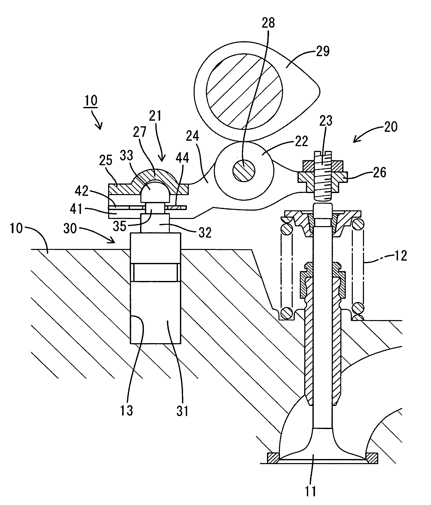
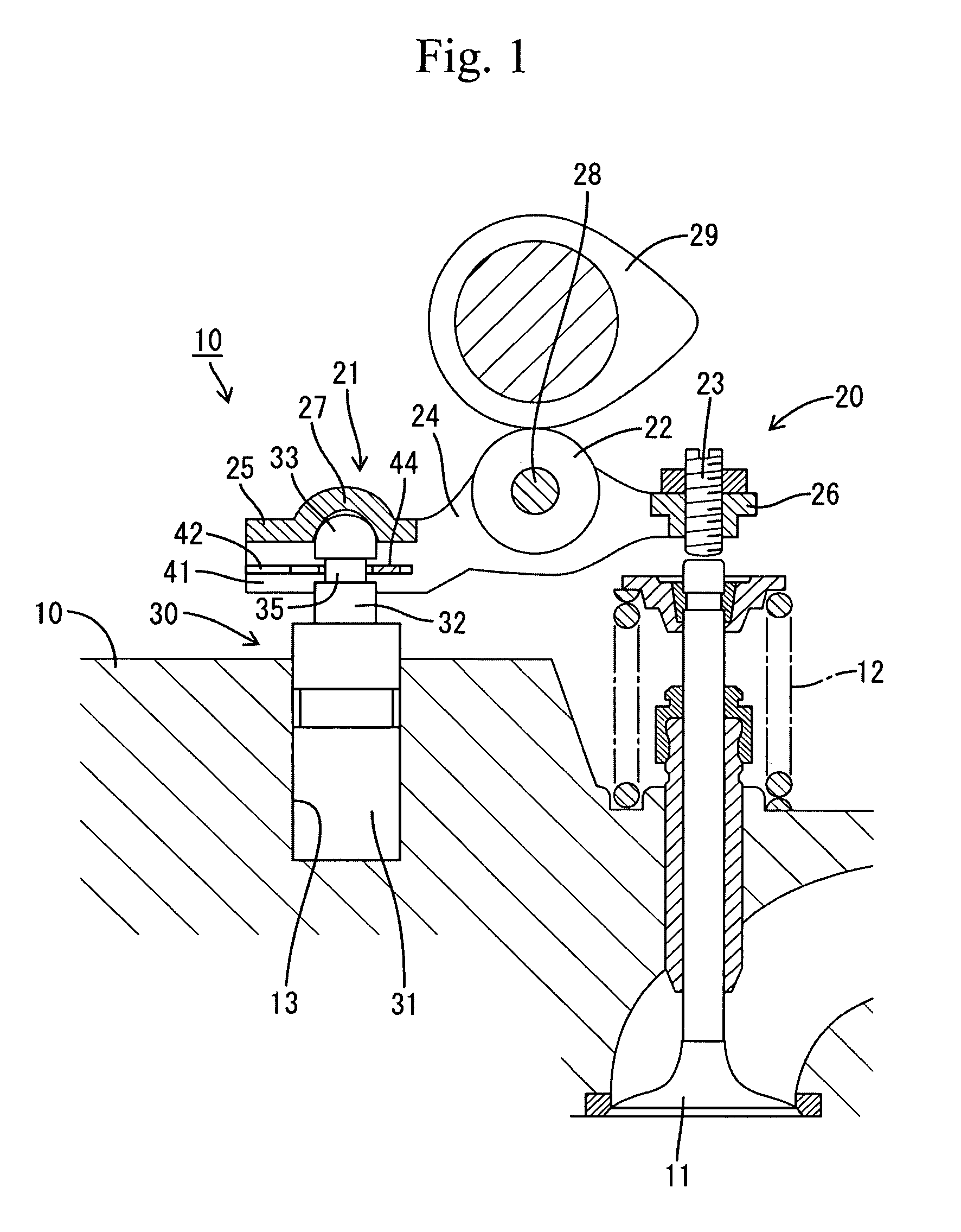
[0020]the present invention will be described with reference to FIGS. 1 to 5. The invention is applied to a valve gear of an internal combustion engine in the embodiment. The valve gear comprises a cylinder head 10 and a valve 11 which is mounted on the cylinder head 10 so as be vertically movable between a valve opening position and a valve closing position and so as to be biased by a valve spring 13 in a valve opening direction (upward). The valve 11 has an upper end protruding from an upper surface of the cylinder head 10.

[0021]A metal rocker arm 20 is provided over the cylinder head 10. The rocker 20 includes an arm body 21, a roller 22 mounted on the arm body 21 and an adjusting screw 23 mounted on the arm body 21. The arm body 21 includes a pair of arm portions 24 extending in the front-back direction, a fulcrum 25 connecting rear ends of both arms portions 24 to each other and a connecting portion 26 connecting front ends of the arms 24 to each other. The arm portions 24, the...

second embodiment

[0031]The plunger 32 is inserted through the locker arm 51 from above after the clip 55 has been mounted on the rocker arm 51. The clip 55 is curved in the process of the fitting, whereby the fitting hole 56 is spread thereby to allow the plunger 32 to pass therethrough. The mounting is completed when the inner circumferential edge of the fitting hole 56 has been fitted in the fitting groove 35. In the second embodiment, the recess 53 serving to lock the clip 55 with the walls 52 is formed by pressing parts of the respective walls 52 outward. Consequently, the manufacturing cost of the valve gear can be reduced as compared with the case where the groove is formed by cutting.

[0032]A third embodiment of the invention will now be described with reference to FIG. 7. The third embodiment differs from the first embodiment in forms of the rocker arm 61 constituting the rocker arm unit 60 and the clip 65. The third embodiment is the same as the first embodiment in the other structure of the...


PUM

PropertyMeasurementUnit
anglesaaaaaaaaaa
shapeaaaaaaaaaa
rotationaaaaaaaaaa

Abstract

A valve gear comprises a cylinder head, a supporting member fixed to the cylinder head, a rocker arm which is mounted on the supporting member so as to be placed on the latter, a substantially plate-shaped clip mountable to the rocker arm, the clip having a fitting hole in which an outer periphery of the supporting member is fitted so that the clip is prevented from falling off, a pair of walls which is formed on the rocker arm so as to be opposed to each other with the supporting member being located therebetween, and a pair of locking portions formed in inner faces of the walls so that outer edges of the clip are elastically engaged with the locking portions thereby to be locked, respectively.

Description

CROSS-REFERENCE TO RELATED APPLICATIONS[0001]This application is based upon and claims the benefit of priority from the prior Japanese Patent Application No. 2007-317181 filed on Dec. 7, 2007, the entire contents of which are incorporated herein by reference.BACKGROUND OF THE INVENTION[0002]1. Field of the Invention[0003]The present invention relates to a valve gear and a rocker arm unit.[0004]2. Description of the Related Art[0005]Internal combustion engines have conventionally been provided with a valve gear comprising a cylinder head, a supporting member fixed to the cylinder head, a rocker arm which is placed on the supporting member so as to be vertically rocked by a cam with the rocker arm serving as a fulcrum thereby to open and close a valve. Since the rocker arm is only placed on the supporting member, there is a possibility that the rocker arm may detach from the supporting member. Furthermore, when to be mounted on the cam and the valve, the rocker arm also tends to easil...

Claims


Application Information

Patent Timeline
Patent Type & Authority Applications(United States)
IPC IPC(8): F01L1/18
CPCF01L1/18F01L1/185F01L1/2405Y10T29/49295F01L2001/187Y10T74/20882F01L1/46
Inventor HIRAMATSU, NAOKI
Owner OTICS CORP
Why Eureka
Try Eureka