
Valve operating system for variable displacement internal combustion engine

a technology of variable displacement and operating system, which is applied in the direction of valve arrangement, machines/engines, mechanical equipment, etc., can solve the problems of limited movement of the valve arm in a direction away from the valve stem, and achieve the effect of accurate and rapid engagement and disengagemen

Inactive Publication Date: 2009-06-11
FORD GLOBAL TECH LLC
View PDF11 Cites 4 Cited by
  • Summary
  • Abstract
  • Description
  • Claims
  • Application Information

AI Technical Summary

Benefits of technology

[0013]It is an advantage of a system according to the present invention that the present valve arm may be precisely located for accurate and rapid engagement and disengagement with a cam arm driven by one of the lobes on a camshaft.
[0014]It is another advantage of a system according to the present invention that noise associated with the operation of the valve arm positioner is mitigated by the use of hydraulically damped elements within the system.
[0015]It is yet another advantage of a system according to the present invention that the system may be used advantageously with a hydraulic lash adjustor incorporated in the valve arm.
[0016]It is yet another advantage of a system according to the present invention that wear problems inherent with prior art systems will be eliminated.

Problems solved by technology

In this manner, movement of the valve arm in a direction away from the valve stem will be limited, but with a hydraulic damping component to the limiting force.

Method used


Image

  • Valve operating system for variable displacement internal combustion engine
  • Valve operating system for variable displacement internal combustion engine
  • Valve operating system for variable displacement internal combustion engine

Examples


Embodiment Construction

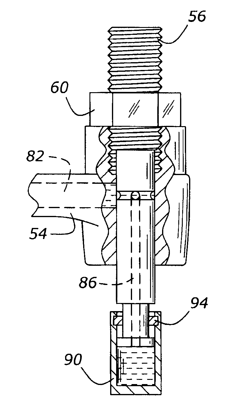
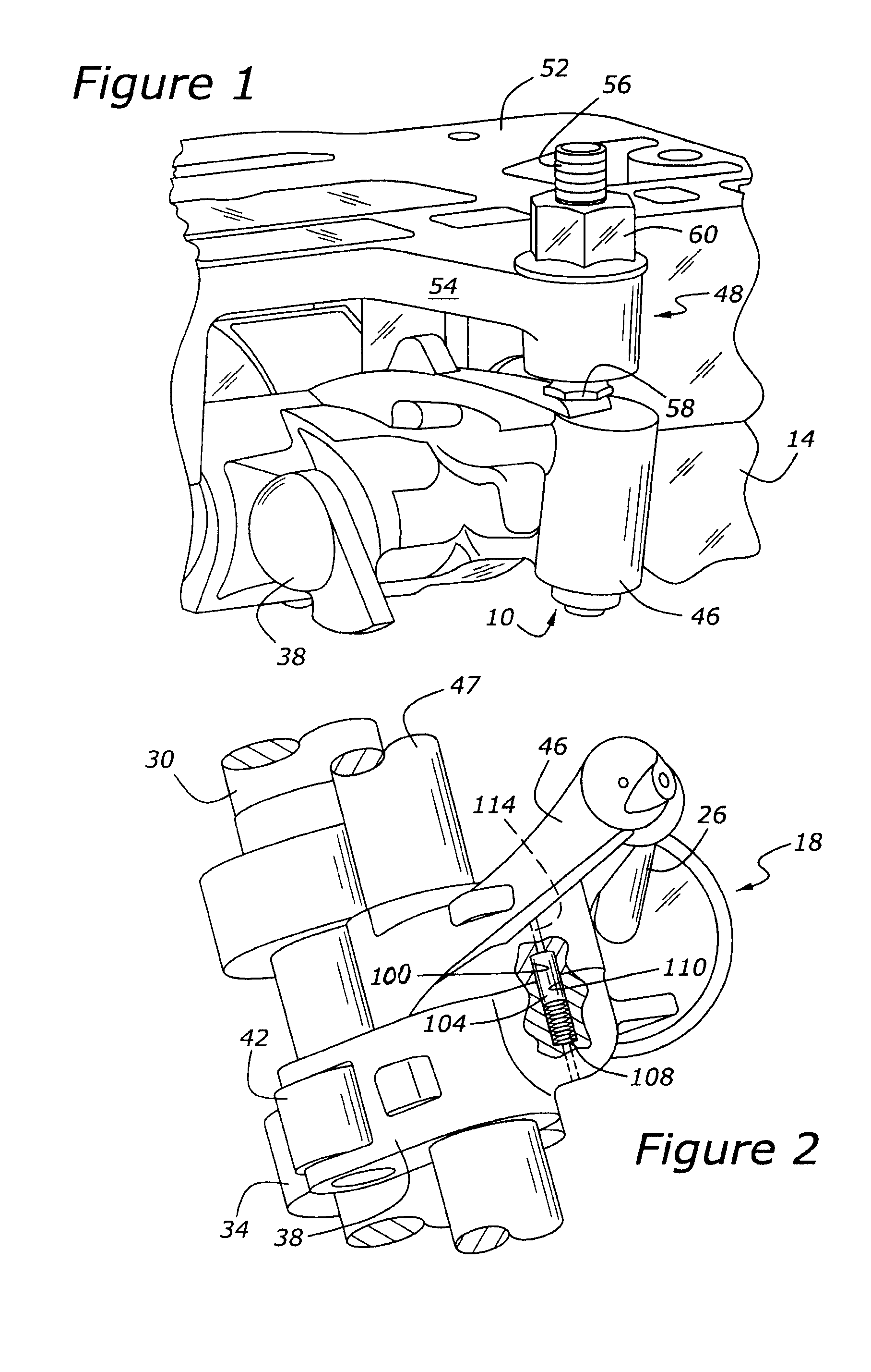
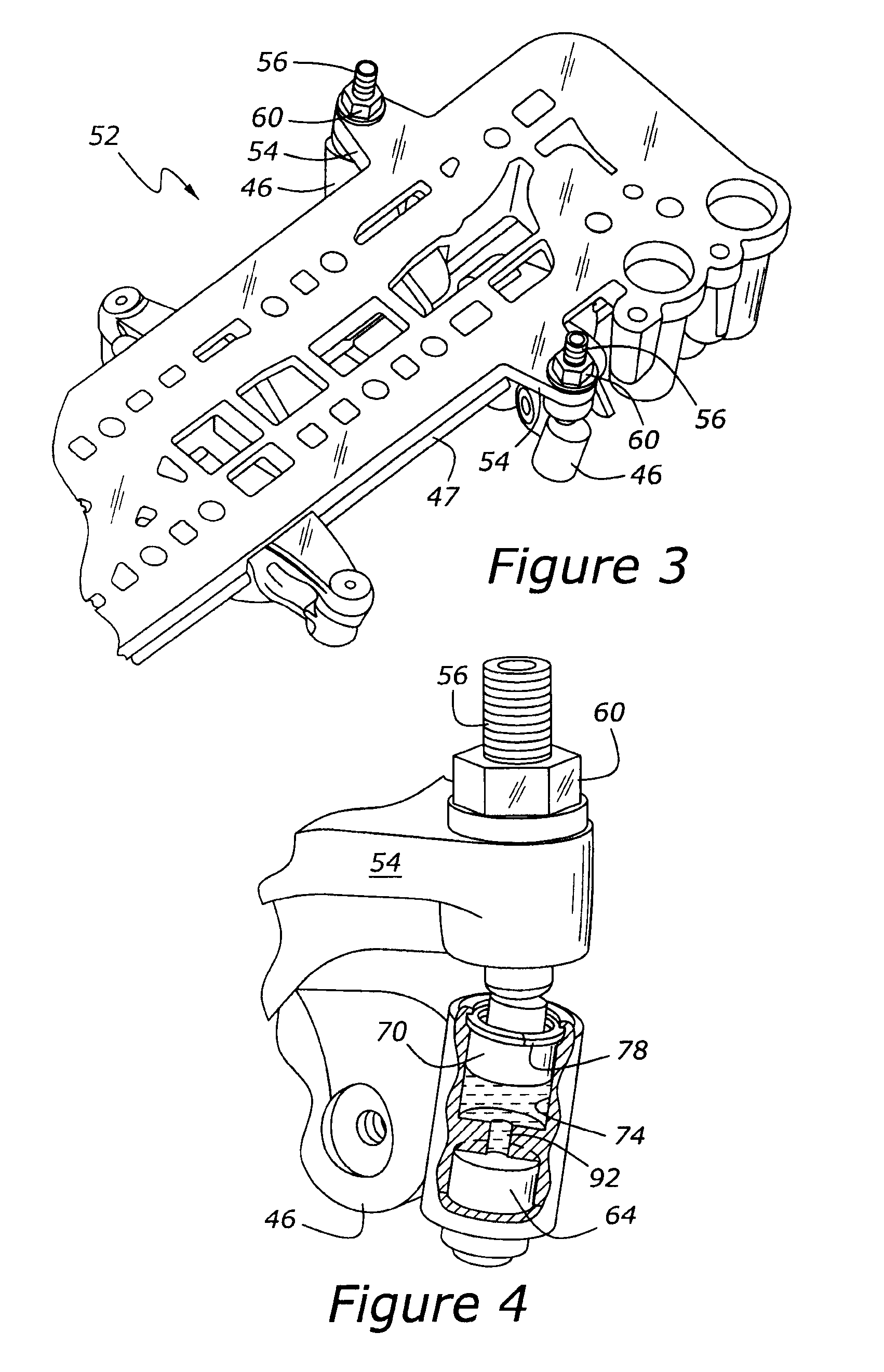
[0024]As shown in FIG. 1, a cylinder valve operating system, 10, is mounted upon a cylinder head, 14, of an engine. The system itself is contained within a ladder frame, 52, (FIG. 3) but those skilled in the art will appreciate in view of this disclosure that the present system could be employed not only with the illustrated ladder frame but with other structures such as camshaft caps having a cantilevered beam or mounting boss similar to beam 54, which provides a mounting position for valve arm positioner 48. Valve arm positioner 48 is shown in FIG. 1 as including a threadably adjustable contactor 56 and a locking nut 60. The lower portion of threadably adjustable contactor 56 has a head, 58, which contacts a load bearing surface on the upper surface of valve arm 46. Valve arm 46 has a hydraulic lash adjuster, shown at 64 in FIG. 4, which contacts the tip of valve stem 26 as shown in FIG. 2. FIG. 1 also shows a cam arm, 38, which is shown in greater detail in FIG. 2. Those skilled ...


PUM


Abstract

A cylinder valve operating system for a variable displacement internal combustion engine having poppet valves includes a cam arm driven by a camshaft and a valve arm selectively driven by the cam arm. A valve arm positioner, which may be hydraulically cushioned, adjustably maintains the valve arm in contact with the valve stem when the valve arm is not being driven by the cam arm, in order that the valve arm will be accurately located for speedy and precise linkage of the cam arm to the valve arm.

Description

CROSS REFERENCE TO RELATED APPLICATIONS[0001]The present application claims priority to U.S. provisional application entitled SET SCREW ADJUSTMENT DEVICE FOR HYDRAULIC VALVETRAIN TO SET ROCKERARM LOCATION having Ser. No. 60 / 992,382 and filed on Dec. 5, 2007.BACKGROUND OF THE INVENTIONField of the Invention[0002]The present invention relates to a reciprocating internal combustion engine having one or more poppet valves which may be disabled so as to allow the engine to be operated with fewer than the total number of cylinders.[0003]Variable displacement engines have been the subject of much inventive activity during the past several decades. Typically, variable displacement systems have included such devices as hydraulically and electromagnetically driven poppet valves, and yet more complicated systems for allowing cylinder poppet valves to be disabled in deactivated cylinders. Cylinder deactivation, in general, is desirable because the fuel economy of an engine may be enhanced by op...

Claims


Application Information

Patent Timeline
IPC IPC(8): F01L1/24
CPCF01L13/0005F01L1/18F01L13/0015F02D13/06
Inventor MORELLI, ANTHONYROBINSON, JOHN W.
Owner FORD GLOBAL TECH LLC
Learn More