Fuel supply system having fuel filter installed downstream of feed pump

a fuel supply system and feed pump technology, applied in the direction of liquid fuel feeders, fuel injecting pumps, machines/engines, etc., can solve the problems of increased possibility of fuel filter clogging, increased pressure loss, and decreased performance or failure of feed pump operation

Active Publication Date: 2009-06-11
DENSO CORP
View PDF8 Cites 35 Cited by
  • Summary
  • Abstract
  • Description
  • Claims
  • Application Information

AI Technical Summary

Benefits of technology

[0011]It is an object of the invention to provide a simple structure of a fuel supply system for vehicles which is equipped with a fuel filter disposed downstream of a feed pump working to pump fuel out of a fuel tank and designed to ensure the mountability thereof in vehicles and may be produced at a low cost.
[0013]Specifically, the control valve serves as a pressure control valve to stabilize or keep the pressure of fuel between the fuel filter and the flow rate control valve at a desired level and a relief valve to control the flow rate of the fuel flowing into the fuel filter. This results in a simplified structure of the fuel supply system which may be produced at a low cost and also improves the mountability of the fuel supply system in vehicles.
[0018]When it is required to prime the fuel in the fuel filter, and the pressure of fuel, as pumped by the priming pump, rises, the control valve opens the return path to supply the fuel to the fuel filter. This eliminates the need for an additional priming bypass filter and a check valve.

Problems solved by technology

This, however, gives rise to the problem of increasing a loss of the pressure of fuel passing through the fuel filter and also results in an increased possibility of clogging of the fuel filter.
The fuel usually becomes wax-like at low temperatures, thus resulting in an increased loss of the pressure of the fuel passing through the fuel filter, which leads to decreased performance or failure in operation of the feed pump.
The fuel supply system in which the fuel filter is disposed downstream of the feed pump, however, encounters the drawback in that a total production cost is increased due to two factors, as discussed below.
It is easy for the fuel supply pump in which the fuel filter is disposed downstream of the feed pump to fill the fuel pipe with the fuel between the fuel tank and the feed pump, but however, it is difficult to fill the fuel filter with the fuel because the feed pump installed upstream of the fuel filter is small in area of an internal fuel path thereof.
The fuel supply system is, therefore, designed to have a bypass path extending directly to the fuel filter to fill the fuel filter with the fuel and a check valve installed in the bypass path, which leads to the increase in production cost of the fuel supply system.
The use of the pressure control valve, the relief valve, the bypass path, and the check valve also results in a complicated structure of the fuel supply system and decreased mountability thereof in the vehicle.

Method used


Image

  • Fuel supply system having fuel filter installed downstream of feed pump
  • Fuel supply system having fuel filter installed downstream of feed pump
  • Fuel supply system having fuel filter installed downstream of feed pump

Examples


first embodiment

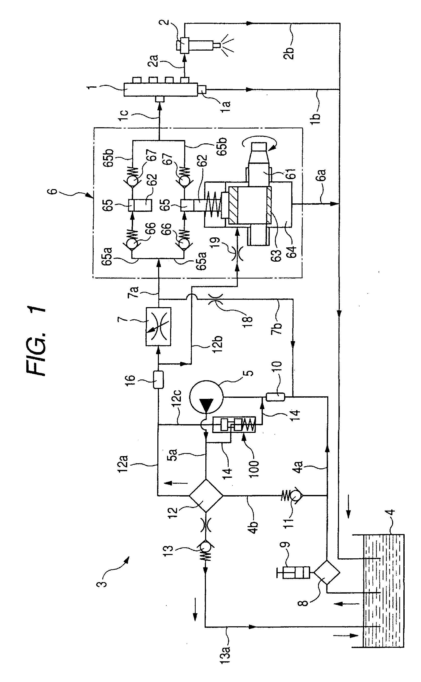
[0039]Referring to the drawings, wherein like reference numbers refer to like parts in several views, particularly to FIG. 1, there is shown an accumulator fuel injection system such as a common rail fuel injection system for automotive diesel engines equipped with a fuel supply system 3 according to the invention.

[0040]The accumulator fuel injection system is used with a four-cylinder diesel engine (not shown) and equipped with a common rail 1, fuel injectors 2 (only one is illustrated), and the fuel supply system 3. The fuel injectors 2 are installed one for each cylinder of the diesel engine and work to spray the fuel, as supplied from the common rail 1, into the engine. The fuel supply system 3 supplies the fuel to the common rail 1.

[0041]The common rail 1 works as an accumulator to store the fuel, as delivered from the fuel supply system 3, at a controlled target pressure which is determined by an electronic control unit (ECU) not shown as a function of an operating condition o...

fourth embodiment

[0091]FIG. 8 illustrates an accumulator fuel injection system for automotive diesel engines equipped with a fuel supply system 3 according to the invention. The same reference numbers as employed in the above embodiments will refer to the same parts, and explanation thereof in detail will be omitted here.

[0092]The fuel supply system 3 is designed to have the return path 14 connecting at an end thereof to between the feed pump 5 and the fuel filter 12 and at the other end thereof to between the priming pump 9 and the feed pump 5. The fuel supply system 3 does not have the bypass pat 4b and the check valve 11 which are used in the first embodiment.

[0093]FIG. 9 is a partially enlarged view which shows an internal structure of the control valve 100 installed in the fuel supply system 3 of FIG. 8. FIG. 10(a) is a longitudinal sectional view which illustrates the first and second valve elements 160 and 170 installed in the control valve 100 of FIG. 9. FIG. 10(b) is a bottom view of FIG. 1...


PUM


Abstract

A fuel supply system for an accumulator fuel injection system designed to inject fuel, as stored in an accumulator, into an internal combustion engine through a fuel injector The fuel supply system includes a feed pump working to pump the fuel out of a fuel tank and a fuel filter disposed between the feed pump and a high-pressure pump working to deliver the fuel to the accumulator. The fuel supply system also includes a return path and a control valve. When the pressure of the fuel between the fuel filter and the flow rate control valve exceeds a first set pressure, the control valve opens the return path to return the fuel from downstream to upstream of the feed pump to keep the pressure of fuel supplied to the flow rate control valve below the first set pressure, thereby controlling the flow rate of the fuel passing through the fuel filter.

Description

CROSS REFERENCE TO RELATED DOCUMENT[0001]The present application claims the benefit of Japanese Patent Application No. 2007-314629 filed on Dec. 5, 2007, the disclosures of which are incorporated herein by reference.BACKGROUND OF THE INVENTION[0002]1. Technical Field of the Invention[0003]The present invention relates generally to a fuel supply system which may be employed in automotive common rail fuel injection systems, and more particularly to such a fuel supply system which is equipped with a fuel filter installed downstream of a feed pump and designed to have a simple structure which ensures the mountability thereof in vehicles and may be produced at a low cost.[0004]2. Background Art[0005]Typical fuel supply systems for use in accumulator fuel injection systems for diesel engines are equipped with a high-pressure pump, a feed pump, a suction control valve (i.e., a flow rate control valve), and a fuel filter. The high-pressure pump works to pressurize and deliver fuel to a comm...

Claims


Application Information

Patent Timeline
Patent Type & Authority Applications(United States)
IPC IPC(8): F02M63/00F02M37/32
CPCF02M37/0029F02M37/0052F02M63/0225F02M59/34F02M37/22F02M37/16F02M37/32
Inventor SANO, ATSUSHI
Owner DENSO CORP
Why Eureka
Try Eureka