Aerator device inducing cyclonic flow

a technology of cyclonic flow and aerator, which is applied in the direction of liquid transfer device, packaging goods type, liquid handling, etc., can solve the problems of consuming a gallon of diesel fuel per hour in idling trucks, and saving trucking companies a significant expense in reducing idling, so as to improve the airflow velocity and accelerate the unloading of products. , the effect of increasing the speed

Active Publication Date: 2009-06-11
BULK TANK
View PDF19 Cites 13 Cited by
  • Summary
  • Abstract
  • Description
  • Claims
  • Application Information

AI Technical Summary

Benefits of technology

[0021]Still another object of this aerator device for inducing cyclonic flow is to provide for increased airflow velocity during aeration that leads to faster unloading of product.
[0022]Still another object of this aerator device for inducing cyclonic flow is to provide an aerator that fluidizes granular bulk material, or product, for more rapid unloading from a tank trailer or other container.
[0023]Still another

Problems solved by technology

An idling truck often consumes a gallon of diesel fuel per hour.
As diesel fuel prices fluctuate in the vicinity of $4 per gallon,

Method used


Image

  • Aerator device inducing cyclonic flow
  • Aerator device inducing cyclonic flow
  • Aerator device inducing cyclonic flow

Examples


Embodiment Construction

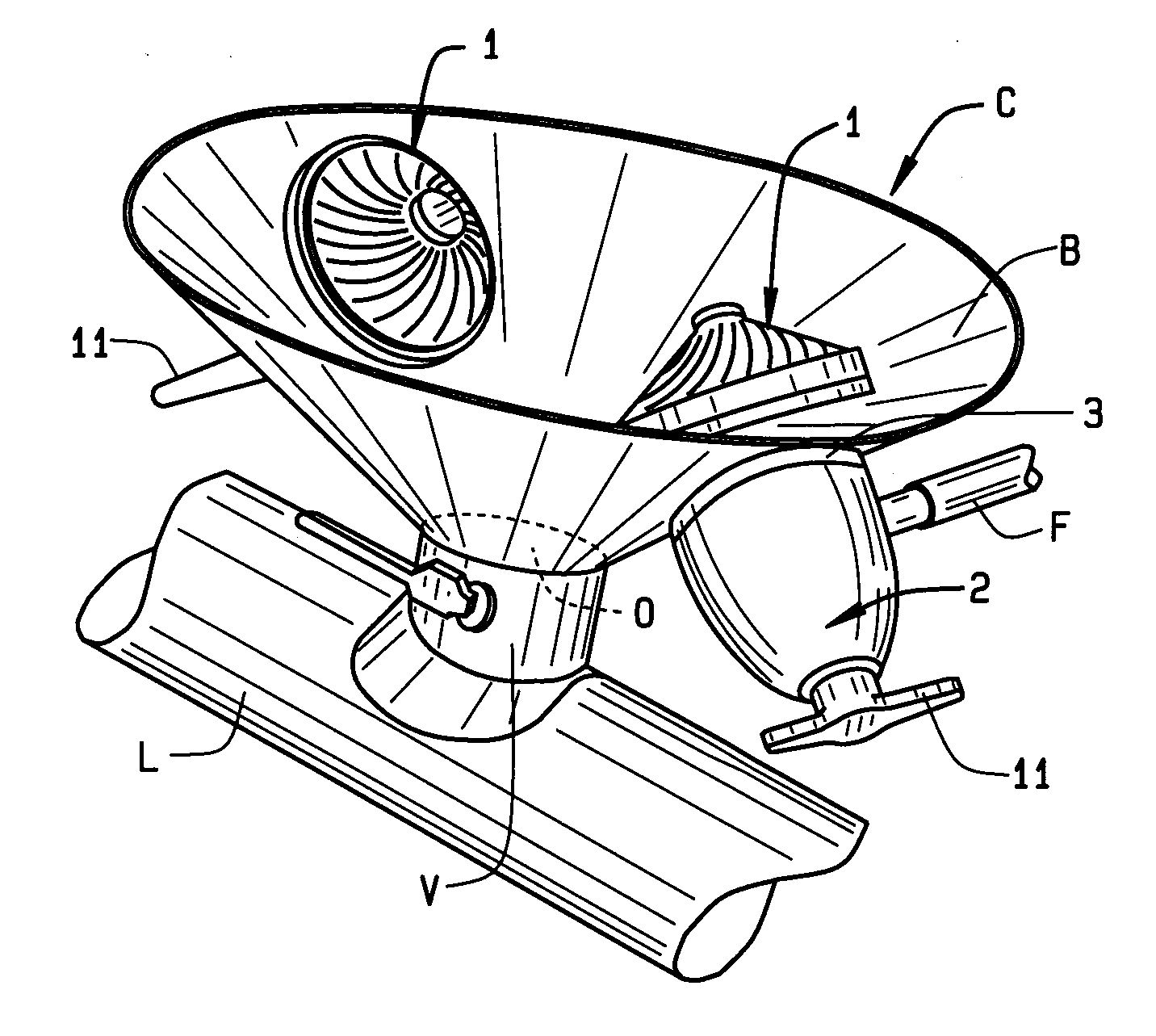
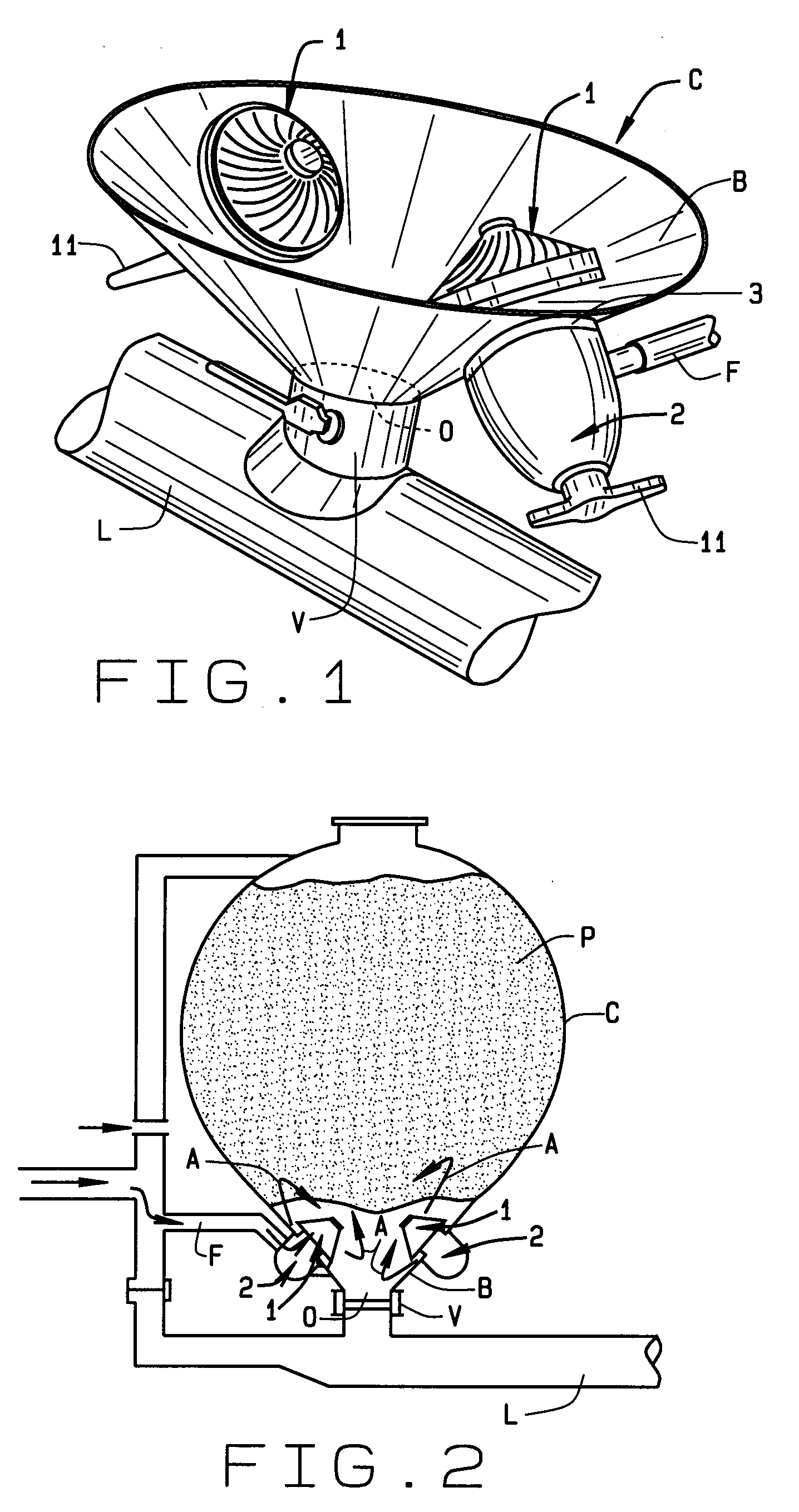
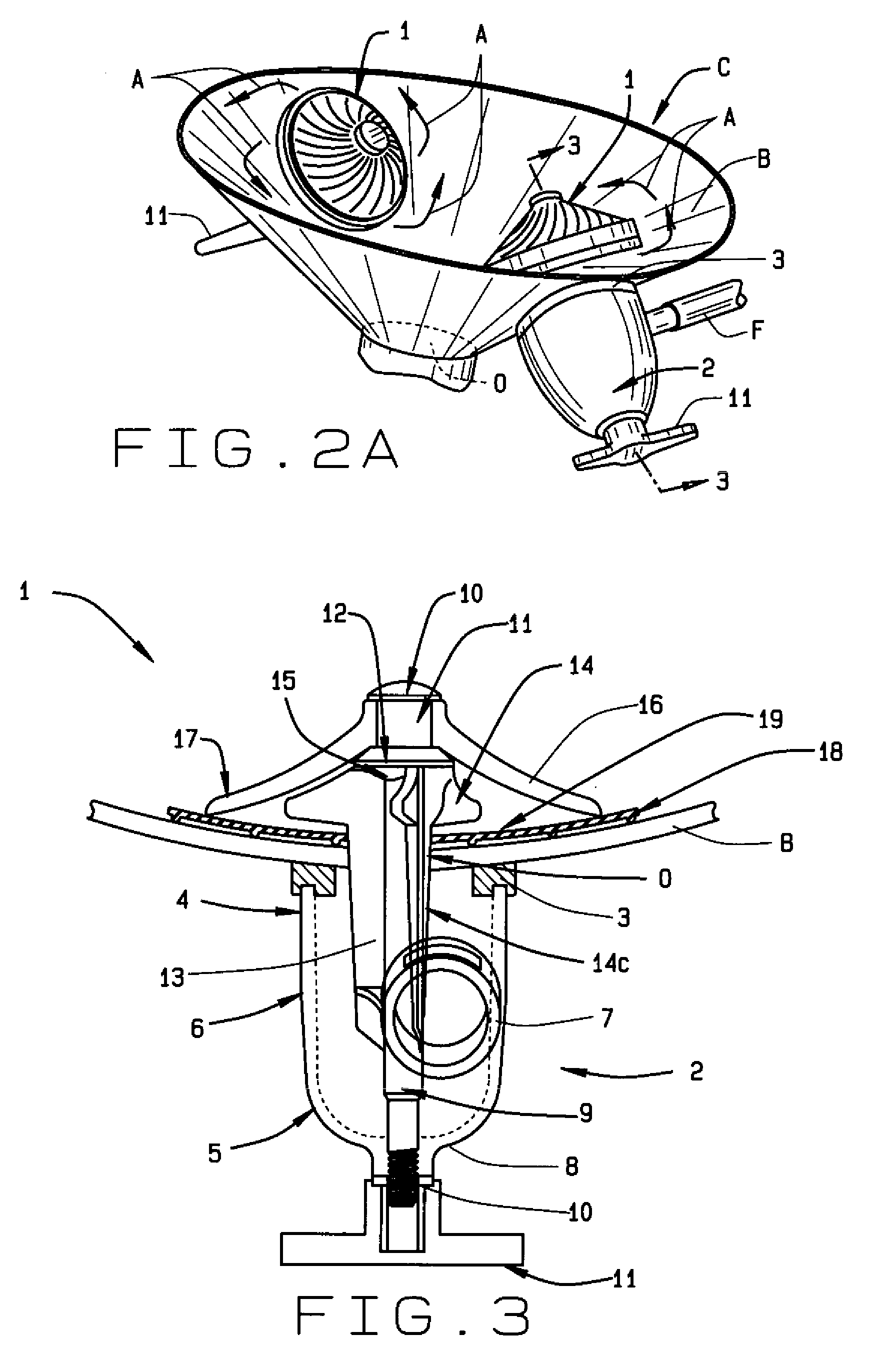
[0048]In referring to the drawings, FIG. 1 shows typical location of the aeration device of the present invention upon a bulk material container. There, a fragmented portion of the bulk material container C, such as a tank trailer, hopper railcar, or other storage chamber, includes a downwardly tapering or conically shaped bottom B having a discharge opening O at the lower end of the hopper, or container bottom, B which leads into a discharge control valve V that releases a controlled rate of bulk granular material, or the like, from the hopper or storage chamber C into a transversely extending discharge line L for distribution into another storage chamber or a transport vehicle. Generally a plurality of aeration devices 1 mount to the container bottom B for effective and symmetric vibration of the bulk materials for unloading from the hopper. While many of the aeration devices 1 may be used, FIG. 1 illustrates two of them in operation.

[0049]Aeration devices 1 in a bulk hopper opera...


PUM

PropertyMeasurementUnit
Lengthaaaaaaaaaa
Thicknessaaaaaaaaaa
Diameteraaaaaaaaaa

Abstract

A pneumatic aerator aids in bulk material unloading, handling and transport using tank trailers, hopper cars, and other containers, as its aerator introduces a cyclonic air flow and vibration into the bulk material. This aerator has a housing, one or three guide tubes, an aerator extending through the housing, a gasket upon one end of the aerator generally within the container of the bulk material, and an optional wearplate beneath the gasket. The aerator has a stem with one vane, preferably three vanes, where the vanes and contiguous fins curve counterclockwise in a helical manner. The airflow past the fins and vanes acquires a counterclockwise rotation, rotating the air as it exits radially from the gasket increasing the bulk material unloaded per hour. This aerator also has various gasket thicknesses and edge conditions, guide tubes, and various shapes in the vanes and fins for alternate speeds and directions of airflow. This aerator increases the rate of unloading of bulk materials from tank trailers, hopper cars, and various containers and transporters.

Description

CROSS REFERENCE TO RELATED APPLICATION[0001]This non-provisional application claims priority to the provisional application having Ser. No. 61 / 012,883 filed on Dec. 11, 2007 and is commonly owned by the same inventor.[0002]This application is related to U.S. Pat. Nos. 5,017,053, 5,988,867 and 6,170,976 from the same inventor.BACKGROUND OF THE INVENTION[0003]This invention relates generally to bulk material handling, and more specifically pertains to an aerator that pressurizes a storage container and fluidizes bulk material to flow from that storage container into a delivery system. The invention is especially useful for unloading a tank trailer hauling granular bulk material.[0004]The discharge of bulk material granules from a storage chamber can result in blockage of the exit from the storage chamber or other interruptions in the flow of material which cause various conditions such as arching, bridging, “rat-holing” and the like. Storage chambers exist in various types of equipmen...

Claims


Application Information

Patent Timeline
IPC IPC(8): B65B1/16B01F33/40
CPCB65G53/22B65D88/706
Inventor SISK, DAVID E.
Owner BULK TANK
Why Eureka
Try Eureka