Torque Control for Hybrid Electric Vehicle Speed Control Operation

a technology of torque control and hybrid electric vehicles, applied in process and machine control, vehicle sub-unit features, instruments, etc., can solve the problems of shortened lifespan, increased wear, and disclosure of disadvantages, and achieve the effects of reducing driveline disturbances, maximizing energy recovery, and minimizing engine braking

Active Publication Date: 2009-06-11
FORD GLOBAL TECH LLC
View PDF39 Cites 161 Cited by
  • Summary
  • Abstract
  • Description
  • Claims
  • Application Information

AI Technical Summary

Benefits of technology

[0001]Vehicles may be configured with a hybrid propulsion system that utilizes at least two different sources of torque for propelling the vehicle. As one non-limiting example, a hybrid propulsion system for a vehicle may be configured as a hybrid electric vehicle (HEV), wherein one or more electric machines and an internal combustion engine may be selectively operated to provide the requested propulsive effort. Similarly, during deceleration of the vehicle, the electric machines and engine can be selectively operated to provide vehicle driveline braking in order to recapture kinetic energy of the vehicle. In particular, the electric machines can be used to absorb torque that may be converted into electric energy which may be stored in a battery in what may be referred to as regenerative braking. In this way, vehicle efficiency may be increased.
[0002]Furthermore, the operating efficiency of a vehicle may be increased by utilizing closed loop feedback control to maintain a set speed or speed profile of a vehicle by selectively providing acceleration and deceleration based on an operating vehicle speed range. In one approach, the speed of a vehicle traveling along a decline or negative gradient may be maintained by providing selective deceleration via the friction brakes of the vehicle and / or engine compression braking.
[0003]However, the inventors of the present disclosure have recognized a disadvantage with the above approaches. In particular, continuous use of the friction brake to maintain a desired speed during a vehicle descent may cause increase wear of the friction brakes resulting in a shortened lifespan. Furthermore, in order to utilize engine compression braking, a state of a fixed-gear ratio transmission may be shifted which may result in driveline disturbances due to abrupt changes in the engine compression brake torque when a transmission down shift occurs. Moreover, due to closed loop feedback control during the vehicle speed control, a state of the transmission may be shifted frequently which may be referred to as shift busyness which may result in reduced drivability of the vehicle.
[0005]By selectively varying the brake torque of the electric energy conversion devices of the hybrid vehicle during vehicle speed control operation in order to decelerate the vehicle to a desired speed, driveline braking may be transmitted to the wheels without a transmission downshift or even delaying a downshift and without use of the friction brakes. In this way, energy recovery may be maximized and engine braking may be minimized, driveline disturbances may also be reduced resulting in improved vehicle drivability and the lifespan of the friction brake may be extended. Furthermore, by taking advantage of the regenerative braking capabilities of the electric energy conversion devices a state of charge of an energy storage device may be increased.

Problems solved by technology

However, the inventors of the present disclosure have recognized a disadvantage with the above approaches.
In particular, continuous use of the friction brake to maintain a desired speed during a vehicle descent may cause increase wear of the friction brakes resulting in a shortened lifespan.
Furthermore, in order to utilize engine compression braking, a state of a fixed-gear ratio transmission may be shifted which may result in driveline disturbances due to abrupt changes in the engine compression brake torque when a transmission down shift occurs.
Moreover, due to closed loop feedback control during the vehicle speed control, a state of the transmission may be shifted frequently which may be referred to as shift busyness which may result in reduced drivability of the vehicle.

Method used


Image

  • Torque Control for Hybrid Electric Vehicle Speed Control Operation
  • Torque Control for Hybrid Electric Vehicle Speed Control Operation
  • Torque Control for Hybrid Electric Vehicle Speed Control Operation

Examples


Embodiment Construction

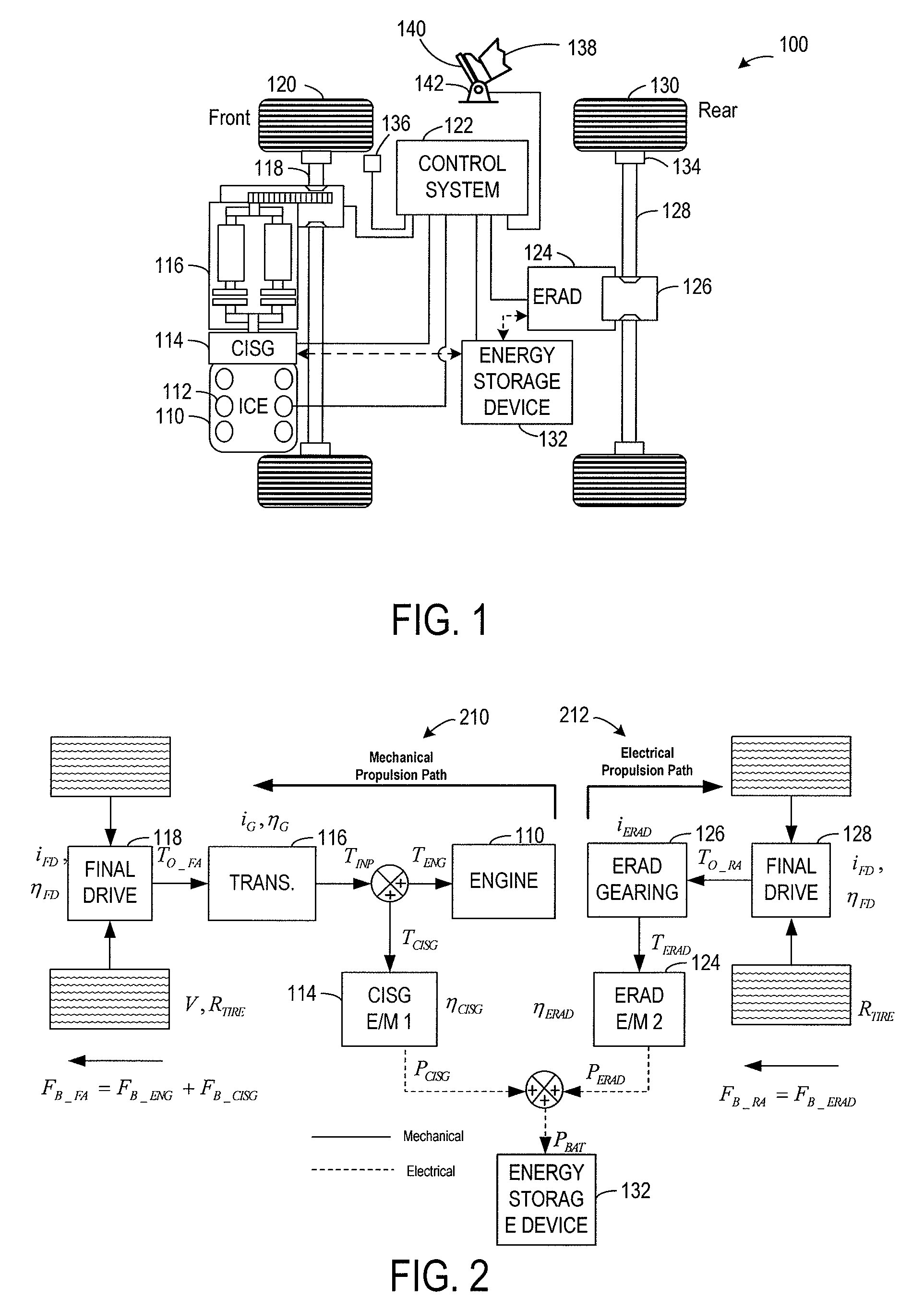
[0013]FIG. 1 illustrates an example hybrid propulsion system 100 for a vehicle. In this particular example, hybrid propulsion system 100 is configured as a hybrid electric vehicle (HEV), which may be operated in conjunction with a front wheel drive (FWD) vehicle platform. However, the approaches described herein may be applied to other vehicle platforms including rear wheel drive, four wheel drive, or all wheel drive systems. Hybrid propulsion system 100 includes a powertrain comprising an internal combustion engine (ICE) 110, a first electric energy conversion device 114, a transmission 116 for providing torque to front wheels 120, and a second electric energy conversion device 124 for providing torque to rear wheels 130.

[0014]The first and second electric energy conversion devices may be alternatively referred to as motors and / or generators. It will be appreciated that an electric energy conversion device may be any suitable device for converting electric energy to kinetic energy ...


PUM


Abstract

A hybrid propulsion system for a vehicle. The system including, a transmission device for transmitting torque to a first at least one drive wheel, a first electric energy conversion device coupled to an input of the transmission device, a second electric energy conversion device for transmitting torque to a second at least one drive wheel, and a control system, during a vehicle speed control operation where a speed of the vehicle is maintained at a desired speed, in response to acceleration resulting in vehicle speed beyond the desired speed, the acceleration not caused by vehicle operator input, the control system varying torque output of at least one of the first electric energy conversion device and the second electric energy conversion device to provide brake torque to at least one of the first at least one drive wheel and the second at least one drive wheel to decelerate the vehicle to the desired speed, selection of said one of the first and second electric energy conversion device based on an operating condition.

Description

BACKGROUND AND SUMMARY[0001]Vehicles may be configured with a hybrid propulsion system that utilizes at least two different sources of torque for propelling the vehicle. As one non-limiting example, a hybrid propulsion system for a vehicle may be configured as a hybrid electric vehicle (HEV), wherein one or more electric machines and an internal combustion engine may be selectively operated to provide the requested propulsive effort. Similarly, during deceleration of the vehicle, the electric machines and engine can be selectively operated to provide vehicle driveline braking in order to recapture kinetic energy of the vehicle. In particular, the electric machines can be used to absorb torque that may be converted into electric energy which may be stored in a battery in what may be referred to as regenerative braking. In this way, vehicle efficiency may be increased.[0002]Furthermore, the operating efficiency of a vehicle may be increased by utilizing closed loop feedback control to...

Claims


Application Information

Patent Timeline
Patent Type & Authority Applications(United States)
IPC IPC(8): B60K1/00G06F7/00B60W30/18
CPCB60K1/02Y02T10/642B60K6/442B60K6/485B60K6/52B60K6/547B60L2240/423B60L2240/425B60W10/06B60W10/08B60W10/11B60W10/113B60W10/115B60W20/00B60W30/146B60W30/18109B60W30/18127B60W2510/087B60W2510/244B60W2520/10B60W2520/26B60W2520/263B60W2540/10B60W2540/12B60W2710/0666B60W2710/083B60W2720/10B60Y2400/428Y02T10/6226Y02T10/6234Y02T10/6265Y02T10/6286B60K6/365Y02T10/62Y02T10/64B60W20/30B60W20/13
Inventor SOLIMAN, IHAB S.ASWANI, DEEPAK
Owner FORD GLOBAL TECH LLC
Why Eureka
Try Eureka