Method of fabricating light emitting diode package with surface treated resin encapsulant and the package fabricated by the method

Active Publication Date: 2009-06-11
SEOUL SEMICONDUCTOR
View PDF4 Cites 3 Cited by
  • Summary
  • Abstract
  • Description
  • Claims
  • Application Information

AI Technical Summary

Benefits of technology

[0010]The present invention provides a method of fabricating a light emitting diode package capable of preventing an air layer from being formed in an interface between a resin encapsulant and a resin molding member, or preventing the resin molding member from being separated from the resin encapsulant.
[0011]The present invention also provides a light emitting diode package capable of preventing an air layer from being formed in an interface between a resin encapsulant and a resin molding member, or preventing the separation of the resin molding member at the interface.
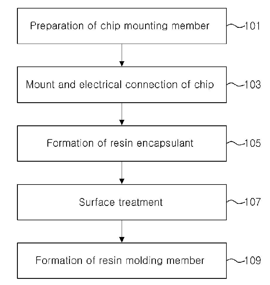
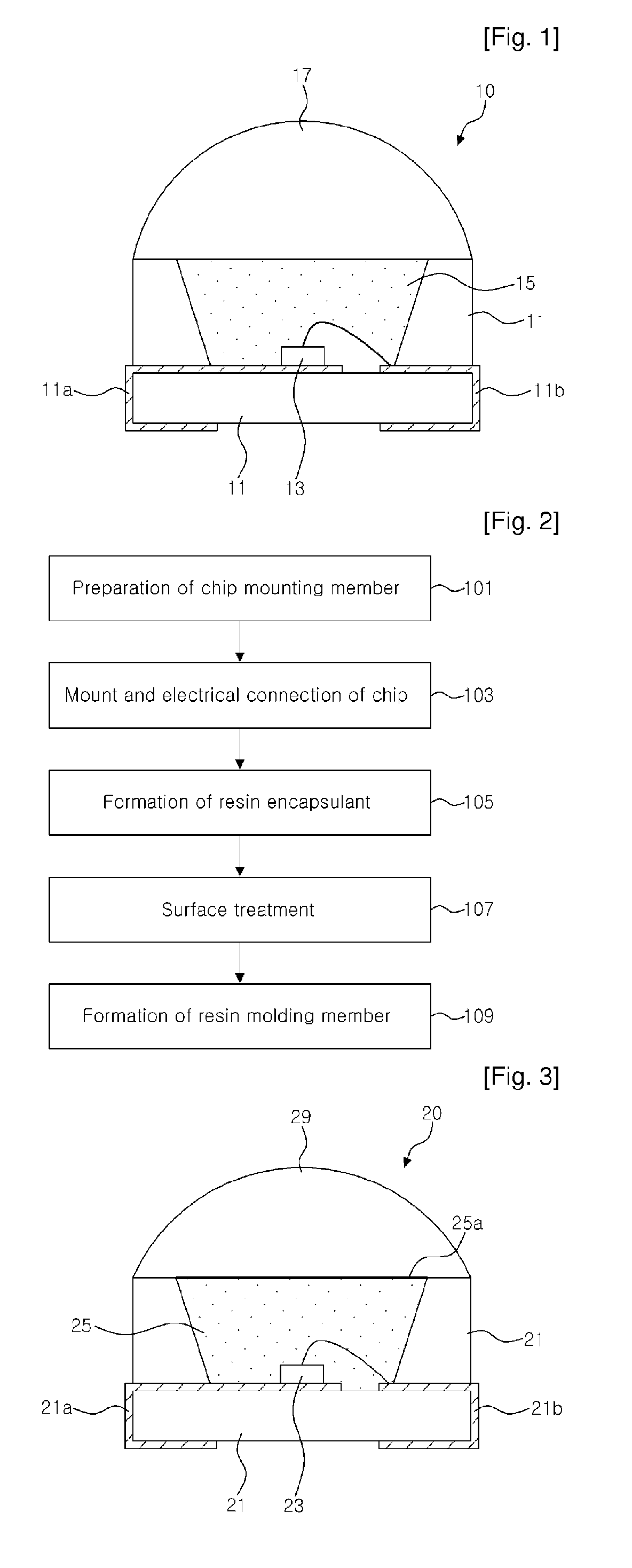
[0013]The present invention discloses a method of fabricating a light emitting diode package that includes preparing a chip mounting member having a mounting surface for mounting a chip thereon. The chip mounting member includes at least two leads insulated from each other. At least one light emitting diode chip is mounted on the mounting surface of the chip mounting member and electrically connected to the at least two leads. Thereafter, a resin encapsulant encapsulating the at least one light emitting diode chip is formed, and the resin encapsulant is surface treated using plasma. Subsequently, a resin molding member covering the surface treated resin encapsulant is formed. Accordingly, a bonding force between the resin encapsulant and the resin molding member is increased, so that an air layer can be prevented from being formed between the resin molding member and the resin encapsulant, and the resin molding member can be prevented from being separated from the resin encapsulant.
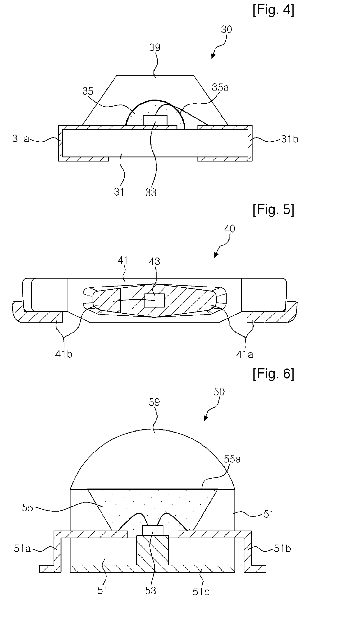
[0014]The present invention also discloses a light emitting diode package having a surface treated resin encapsulant. The light emitting diode package comprises a chip mounting member having a mounting surface for mounting a chip thereon. The chip mounting member comprises two leads insulated from each other. Meanwhile, a light emitting diode chip is mounted on the mounting surface of the chip mounting member. The light emitting diode chip is electrically connected to the leads. A resin encapsulant encapsulates the light emitting diode chip. The resin encapsulant has a surface treated using plasma. A resin molding member covers the resin encapsulant. Accordingly, a bonding force between the surface treated resin encapsulant and the resin molding member is increased, so that an air layer between the resin molding member and the resin encapsulant can be removed, and the resin molding member can be prevented from being separated from the resin encapsulant.

Problems solved by technology

Unfortunately, due to the differences in thermal expansion coefficients of the resin encapsulant and the resin molding member, cracks or deformation of the resin encapsulant occurs.
The air layer formed in the interface between the resin encapsulant and the resin molding member and a space formed due to the separation at the interface change the light radiation characteristic of the light emitting diode package, thereby reducing the life span of the package.

Method used


Image

  • Method of fabricating light emitting diode package with surface treated resin encapsulant and the package fabricated by the method
  • Method of fabricating light emitting diode package with surface treated resin encapsulant and the package fabricated by the method
  • Method of fabricating light emitting diode package with surface treated resin encapsulant and the package fabricated by the method

Examples


Embodiment Construction

[0024]The invention is described more fully hereinafter with reference to the accompanying drawings, in which embodiments of the invention are shown. This invention may, however, be embodied in many different forms and should not be construed as limited to the embodiments set forth herein. Rather, these embodiments are provided so that this disclosure is thorough, and will fully convey the scope of the invention to those skilled in the art. In the drawings, the size and relative sizes of layers and regions may be exaggerated for clarity. Like reference numerals in the drawings denote like elements.

[0025]It will be understood that when an element such as a layer, film, region or substrate is referred to as being “on” another element, it can be directly on the other element or intervening elements may also be present. In contrast, when an element is referred to as being “directly on” another element, there are no intervening elements present.

[0026]FIG. 1 is a sectional view illustrati...


PUM

PropertyMeasurementUnit
Hardnessaaaaaaaaaa

Abstract

Disclosed are a method of fabricating a light emitting diode package with a surface treated resin encapsulant and a package fabricated by the method. According to the method of fabricating a light emitting diode package, a resin encapsulant encapsulating a light emitting diode chip is surface treated using plasma. Thus, a bonding force between the surface treated resin encapsulant and a resin molding member covering it is increased.

Description

CROSS REFERENCE TO RELATED APPLICATIONS[0001]This application is the National Stage of International Application No. PCT / KR2007 / 001614, filed Apr. 3, 2007, and claims priority from and the benefit of Korean Patent Application No. 10-2006-0036071, filed on Apr. 21, 2006, which are both hereby incorporated by reference for all purposes as if fully set forth herein.BACKGROUND OF THE INVENTION[0002]1. Field of the Invention[0003]The present invention relates to a method of fabricating a light emitting diode package and a package fabricated by the method, and more particularly, to a method of fabricating a light emitting diode package with surface treated resin encapsulant and a package fabricated by the method.[0004]2. Discussion of the Background[0005]A light emitting diode has been widely used for indicators, display boards and display devices since the light emitting diode can implement colors. White light can also be implemented, so that the light emitting diode has been used for ge...

Claims


Application Information

Patent Timeline
IPC IPC(8): H01L33/00H01L21/50H01L33/56
CPCB29C45/14639B29L2011/00C08L63/00H01L33/56H01L2224/8592H01L2224/48091H01L2924/00014H01L2924/181H01L2924/00012
Inventor WOO, DO CHOULKIM, MIN HONGKO, MI GYEONG
Owner SEOUL SEMICONDUCTOR
Why Eureka
Try Eureka