Piezoelectric microspeaker using microelectromechanical systems and method of manufacturing the same

Active Publication Date: 2009-06-11
ELECTRONICS & TELECOMM RES INST
View PDF14 Cites 25 Cited by
  • Summary
  • Abstract
  • Description
  • Claims
  • Application Information

AI Technical Summary

Benefits of technology

[0009]The present invention is directed to a microspeaker, which is easy to manufacture, reduces an abrupt fluctuation of power o

Problems solved by technology

However, in a transducer manufactured using piezoelectric MEMS, since a diaphragm has residual tensile stress, a microphone has a relatively low sensitivity,

Method used


Image

  • Piezoelectric microspeaker using microelectromechanical systems and method of manufacturing the same
  • Piezoelectric microspeaker using microelectromechanical systems and method of manufacturing the same
  • Piezoelectric microspeaker using microelectromechanical systems and method of manufacturing the same

Examples


Example

[0021]A piezoelectric microspeaker using microelectromechanical systems (MEMS) according to the present invention will be described more fully hereinafter with reference to the accompanying drawings, in which exemplary embodiments of the invention are shown.

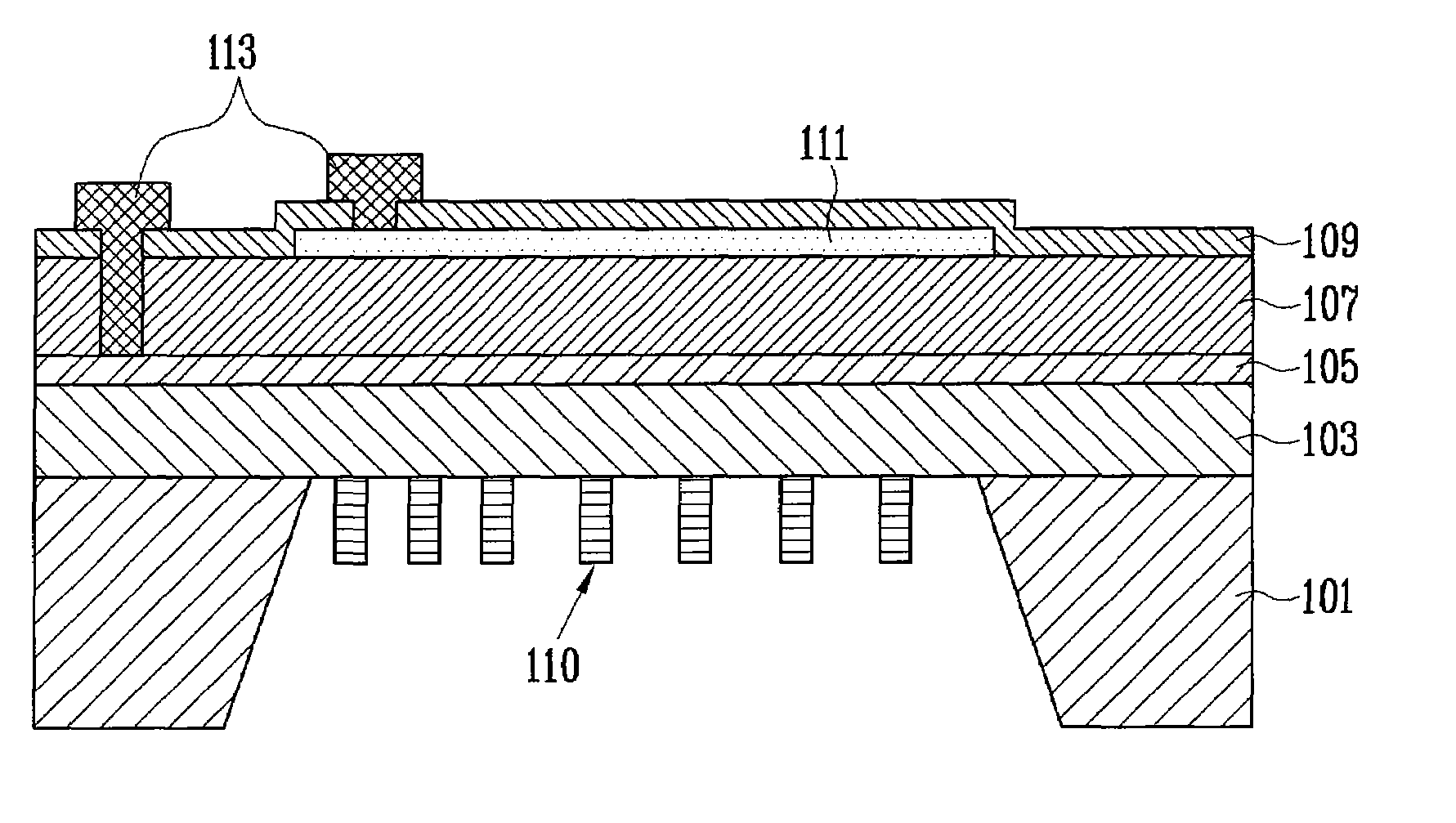
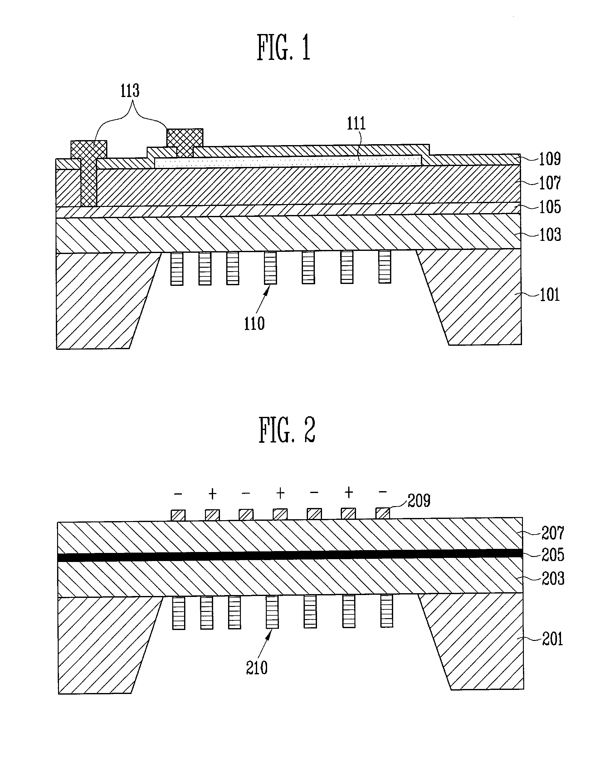
[0022]FIG. 1 is a cross-sectional view of a piezoelectric microspeaker according to an exemplary embodiment of the present invention.

[0023]Referring to FIG. 1, the piezoelectric microspeaker includes a silicon substrate 101, an elastic thin layer 103, a lower electrode layer 105, a piezoelectric layer 107, a blocking layer 109, an upper electrode layer 111, and upper and lower electrodes 113. Also, the piezoelectric microspeaker further includes a resonance change unit 110.

[0024]The piezoelectric microspeaker shown in FIG. 1 has the same construction as a conventional piezoelectric microspeaker having upper and lower electrodes except for the resonance change unit 110.

[0025]Specifically, the silicon substrate 101 functions as a b...


PUM

PropertyMeasurementUnit
Frequencyaaaaaaaaaa
Elasticityaaaaaaaaaa
Piezoelectricityaaaaaaaaaa

Abstract

A piezoelectric microspeaker using microelectromechanical systems (MEMS) and a method of manufacturing the same are provided. The piezoelectric microspeaker includes a piezoelectric layer disposed on an elastic thin layer, and a resonance change unit patterned on one of a bottom surface of the elastic thin layer and a top surface of the piezoelectric layer.

Description

CROSS-REFERENCE TO RELATED APPLICATION[0001]This application claims priority to and the benefit of Korean Patent Application No. 2007-126788, filed Dec. 7, 2007, the disclosure of which is incorporated herein by reference in its entirety.BACKGROUND[0002]1. Field of the Invention[0003]The present invention relates to a piezoelectric microspeaker using microelectromechanical systems (MEMS) and a method of manufacturing the same and, more particularly, to a piezoelectric microspeaker manufactured using MEMS technology, in which a resonance frequency is changed in an audible frequency band, and a method of manufacturing the same.[0004]This work was supported by the IT R&D programs of MIC / IITA. [2006-S-006-02, Components / Module technology for Ubiquitous Terminals][0005]2. Discussion of Related Art[0006]Conventionally, methods of forming a small-sized microphone and a small-sized microspeaker on a silicon wafer using microelectromechanical systems (MEMS) technology have been disclosed. In...

Claims


Application Information

Patent Timeline
IPC IPC(8): H01L41/09H01L41/22
CPCH04R19/005H04R19/02Y10T29/42H01L41/0973H01L41/313H04R31/006H10N30/2047H10N30/073H04R19/04H04R31/00
Inventor LEE, SANG KYUNLEE, SUNG QKIM, HYE JINLEE, JAE WOOPARK, KANG HOKIM, JONG DAE
Owner ELECTRONICS & TELECOMM RES INST
Why Eureka
Try Eureka