

Barrier ribs, plasma display panel including the same, and associated methods
a technology of barrier ribs and plasma display panels, which is applied in the manufacture of electrode systems, electric discharge tubes/lamps, transportation and packaging, etc., can solve the problems of shrinkage of excessive amount of barrier rib material being removed to undercut the barrier rib structure, and generating vibration and noise during the operation of the pdp, so as to reduce vibration and noise and improve the structure
Inactive Publication Date: 2009-06-11
SAMSUNG SDI CO LTD
View PDF10 Cites 2 Cited by
- Summary
- Abstract
- Description
- Claims
- Application Information
AI Technical Summary
Benefits of technology
[0010]It is therefore another feature of an embodiment of the present invention to provide a PDP with barrier ribs having improved structure.
[0011]It is yet another feature of an embodiment of the present invention to provide a PDP having reduced vibrations and noise.
Problems solved by technology
During sandblasting, however, an excessive amount of barrier rib material may be removed to undercut the barrier rib structures, e.g., undercut edges of dummy rib structures in the non-display region.
During baking, binder evaporation from the barrier rib structures may cause shrinkage of the barrier rib structures.
Barrier ribs with such non-uniform structure, i.e., barrier ribs with portions protruding away from the bottom substrate, may cause unstable connection between the dummy barrier ribs and a front panel of the PDP, thereby generating vibration and noise during operation of the PDP.
Method used
View moreImage
Smart ImageViewing Examples

Examples
example 1
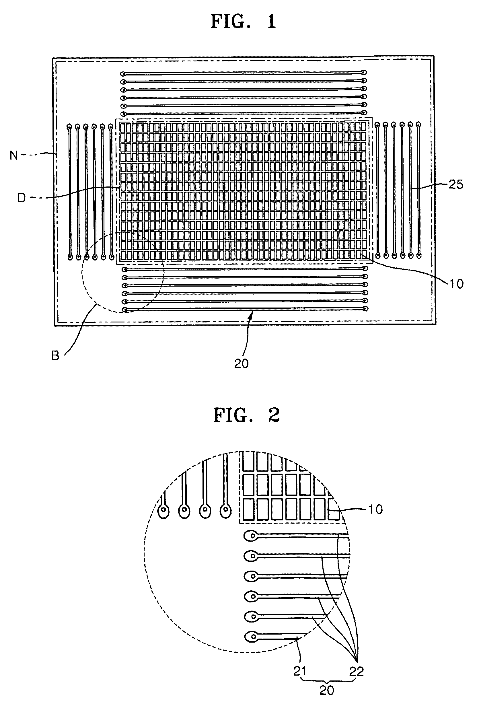
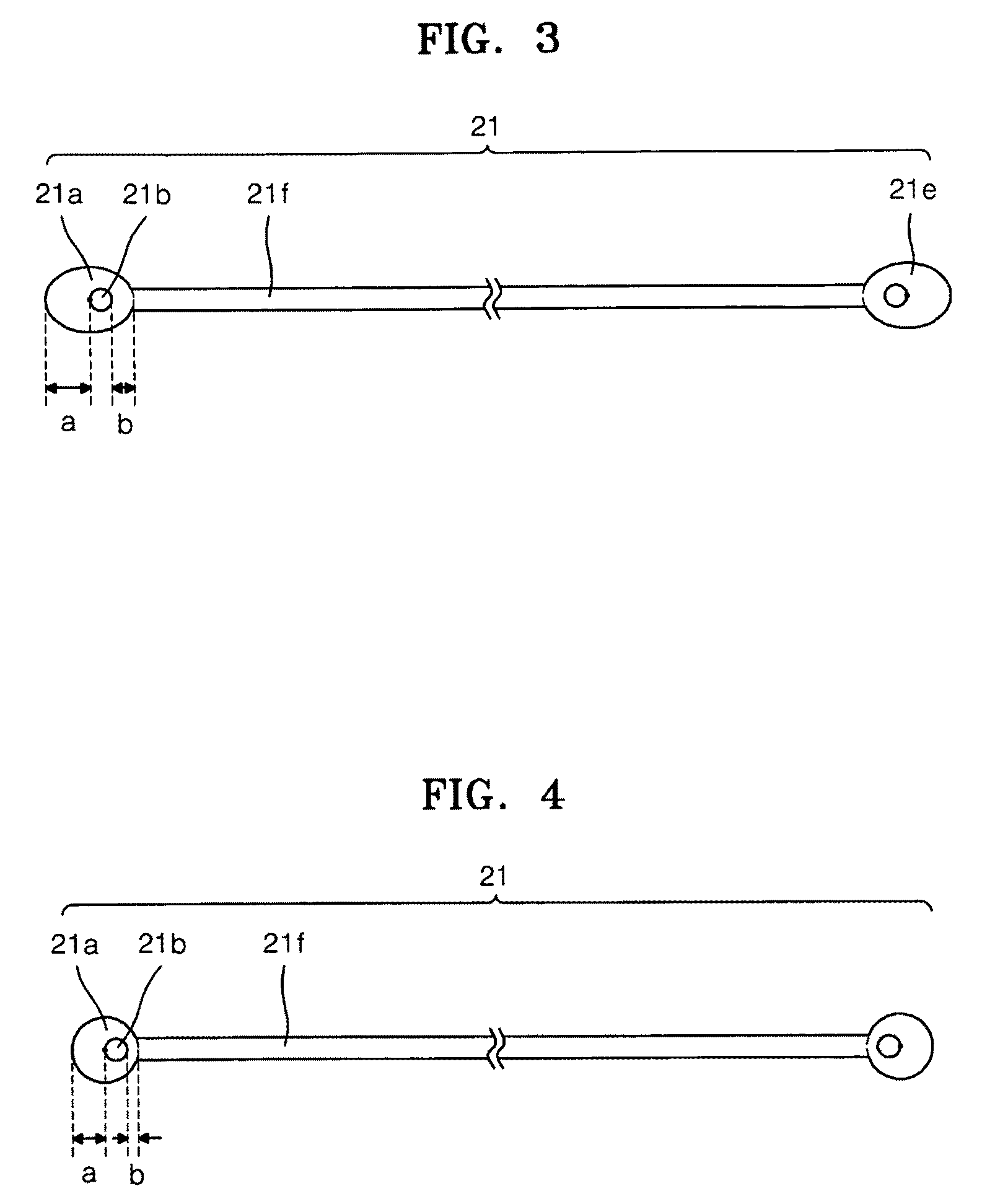
[0049]a first PDP was manufactured with barrier ribs formed according to an embodiment of the present invention, i.e., barrier ribs having curved end portions. In particular, the barrier ribs of the first PDP were formed by using the first and second dummy barrier rib patterning masks 20 and 25 and the inner barrier rib patterning mask 10 according to an embodiment of the present invention, so the dummy barrier ribs were formed to have curved end portions as described previously with reference to FIGS. 7A-7C.
Login to View More PUM
 Abstract
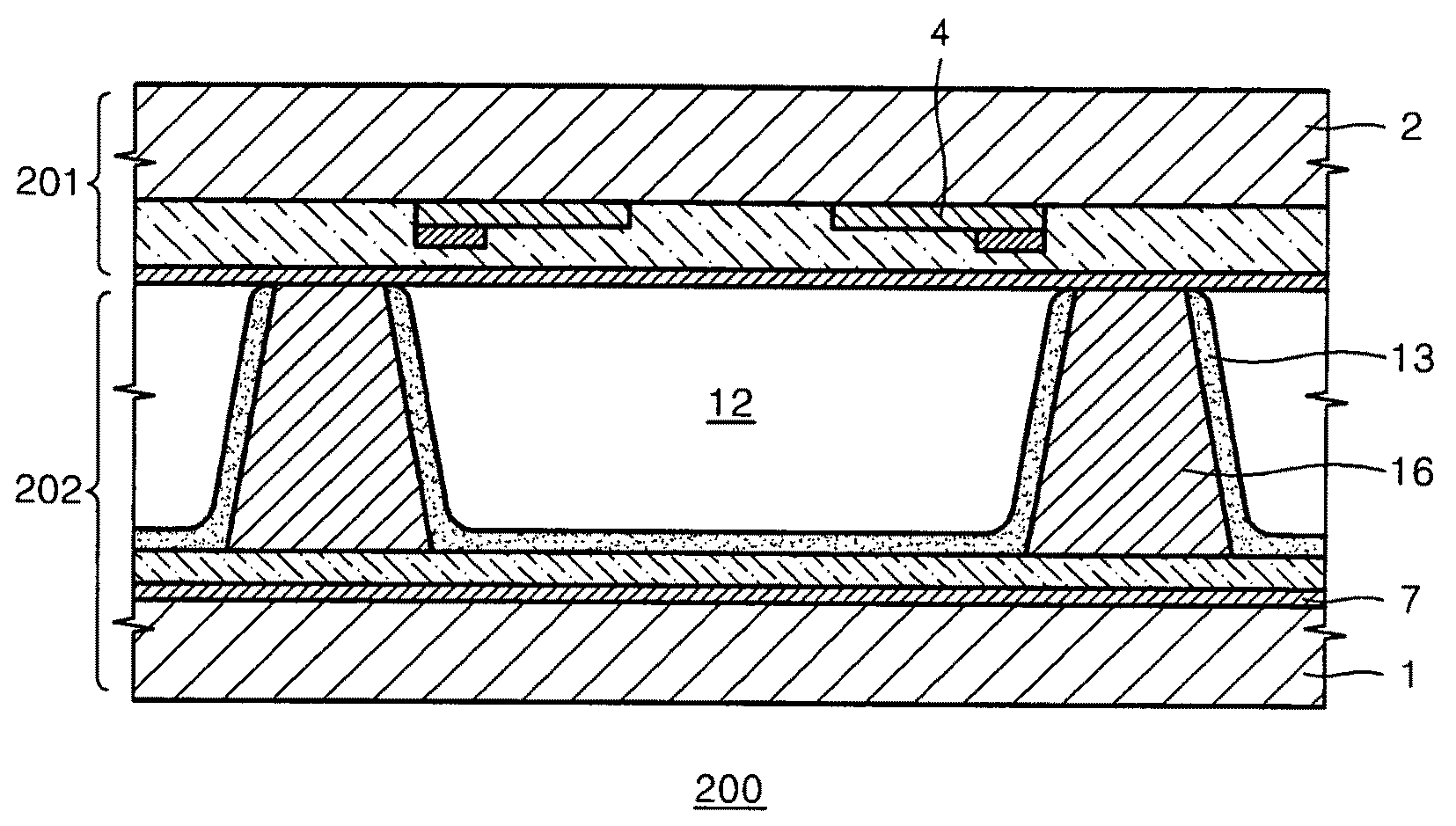
A plasma display panel (PDP) includes a first substrate, a second substrate facing the first substrate, inner barrier ribs in a display region of the PDP between the first substrate and the second substrate to define discharge cells, at least one dummy barrier rib in a non-display region of the PDP between the first substrate and the second substrate, the non-display region being external to the display region, and the dummy barrier rib including at least one curved end portion and a cavity in the curved end portion, discharge electrodes between the first substrate and the second substrate to generate a discharge in the discharge cells, and at least one phosphor layer in each discharge cell.
Description
BACKGROUND OF THE INVENTION[0001]1. Field of the Invention[0002]Embodiments of the present invention relate to a plasma display panel (PDP). More particularly, embodiments of the present invention relate to a method of forming barrier ribs and to a PDP including the same.[0003]2. Description of the Related Art[0004]A PDP may display images by applying voltage via electrodes to a discharge gas in discharge cells between two substrates to generate ultraviolet (UV) light, so the UV light may excite phosphor layers in the discharge cells to trigger emission of visible light. The discharge cells may be defined by barrier ribs between the two substrates, e.g., front and bottom substrates. The barrier ribs may include inner barrier ribs in a display region of the PDP, i.e., a region displaying images, and dummy barrier ribs in a non-display region, i.e., a region outside the display region.[0005]Generally, the barrier ribs may be formed by patterning a dried barrier rib material into a pre...
Claims
Login to View More Application Information
Patent Timeline
 IPC IPC(8): H01J17/49H01J9/20B32B5/00H01J9/02H01J11/22H01J11/34H01J11/36
CPCH01J9/242H01J11/12Y10T428/24479H01J2211/368H01J11/36H01J9/24
InventorHONG, CHONG-GI
OwnerSAMSUNG SDI CO LTD