Step-down switching regulator

a switching regulator and step-down technology, applied in the direction of electric variable regulation, process and machine control, instruments, etc., can solve the problems of large circuit area, poor efficiency when, waste of power consumption, etc., and achieve the effect of stable operation of the microprocessor and reducing the rippling of output voltag

Inactive Publication Date: 2009-06-11
ROHM CO LTD
View PDF4 Cites 38 Cited by
  • Summary
  • Abstract
  • Description
  • Claims
  • Application Information

AI Technical Summary

Benefits of technology

[0017]With such an embodiment, in a case in which the switching operation of the switching device elements is stopped in the light-load state, the second threshold voltage is raised giving consideration to a period in time required for restarting the switching operation. This prevents excessive reduction in the output voltage of the switching regulator, thereby suppressing rippling of the output voltage.
[0029]Such an embodiment prevents excessive reduction in the output voltage of the step-down switching regulator in the light-load state, thereby reducing rippling of the output voltage.
[0031]Such an embodiment reduces rippling of the output voltage of the step-down switching regulator, thereby providing the stable operation of the microprocessor.

Problems solved by technology

Such an arrangement, in which the output voltage is directly supplied to the microprocessor, leads to wasteful power consumption, and accordingly, in general, after the battery voltage is stepped down using a step-down switching regulator, a series regulator, or the like, the constant voltage thus stepped down is supplied to the microprocessor.
However, such an arrangement requires a diode, in addition to an inductor and a capacitor, in the form of external components to a control circuit, leading to a large circuit area.
On the other hand, the latter type provides poor efficiency when a low current is supplied to the load, as compared with the former type.
This leads to wasteful power consumption.
However, in some cases, extreme reduction of the hysteresis range adversely affects the switching control operation.
Furthermore, irregularities in the process for manufacturing the hysteresis comparator lead to irregularities in the hysteresis range.
Accordingly, extreme reduction of the hysteresis range adversely affects the switching control operation due to irregularities in the process of manufacturing the hysteresis.
However, restarting of the switching operation involves a certain delay after stopping of the switching operation in the light-load state.
This leads to increased rippling of the output voltage.

Method used


Image

  • Step-down switching regulator
  • Step-down switching regulator
  • Step-down switching regulator

Examples


Embodiment Construction

[0041]The invention will now be described based on preferred embodiments which do not intend to limit the scope of the present invention but exemplify the invention. All of the features and the combinations thereof described in the embodiment are not necessarily essential to the invention.

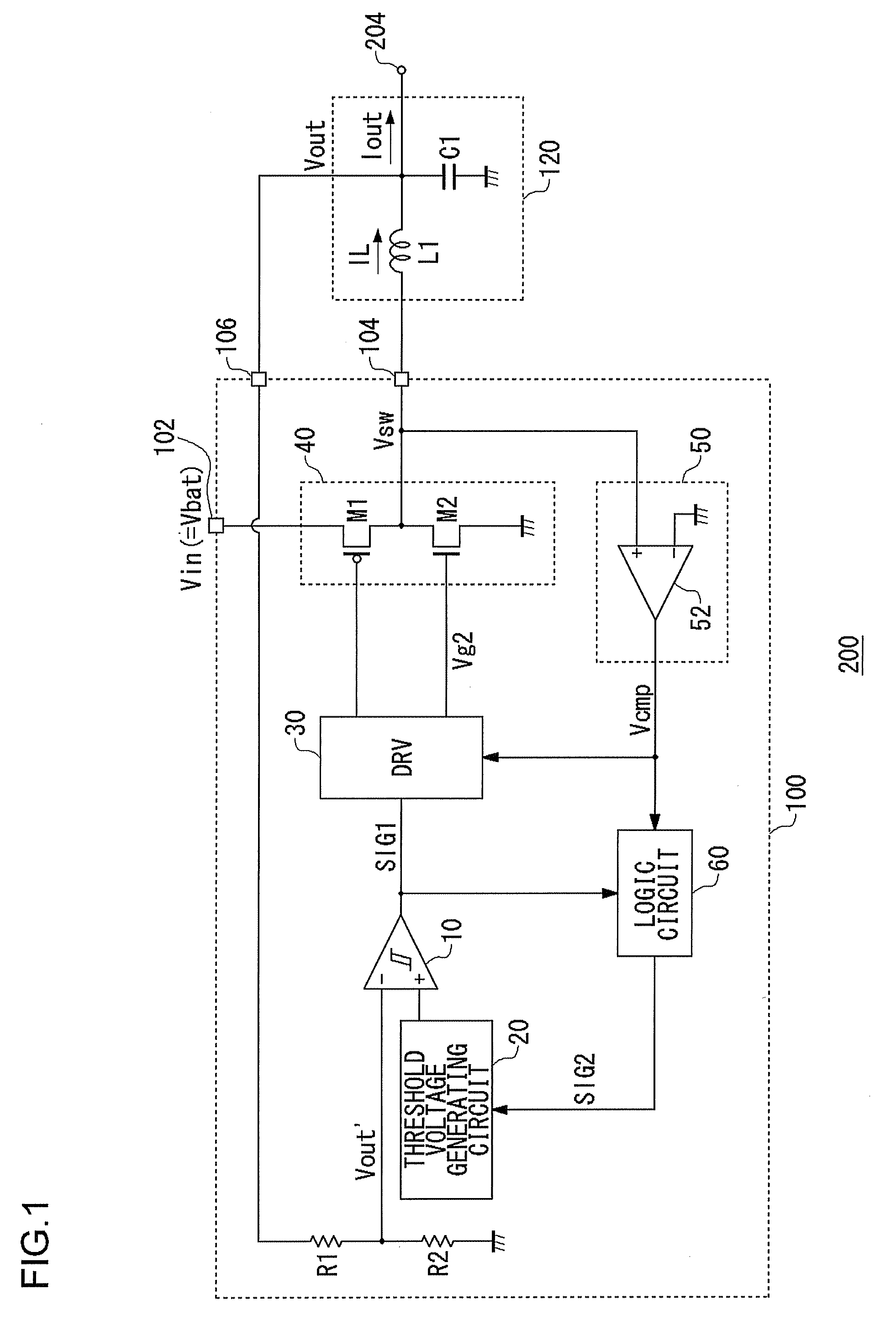
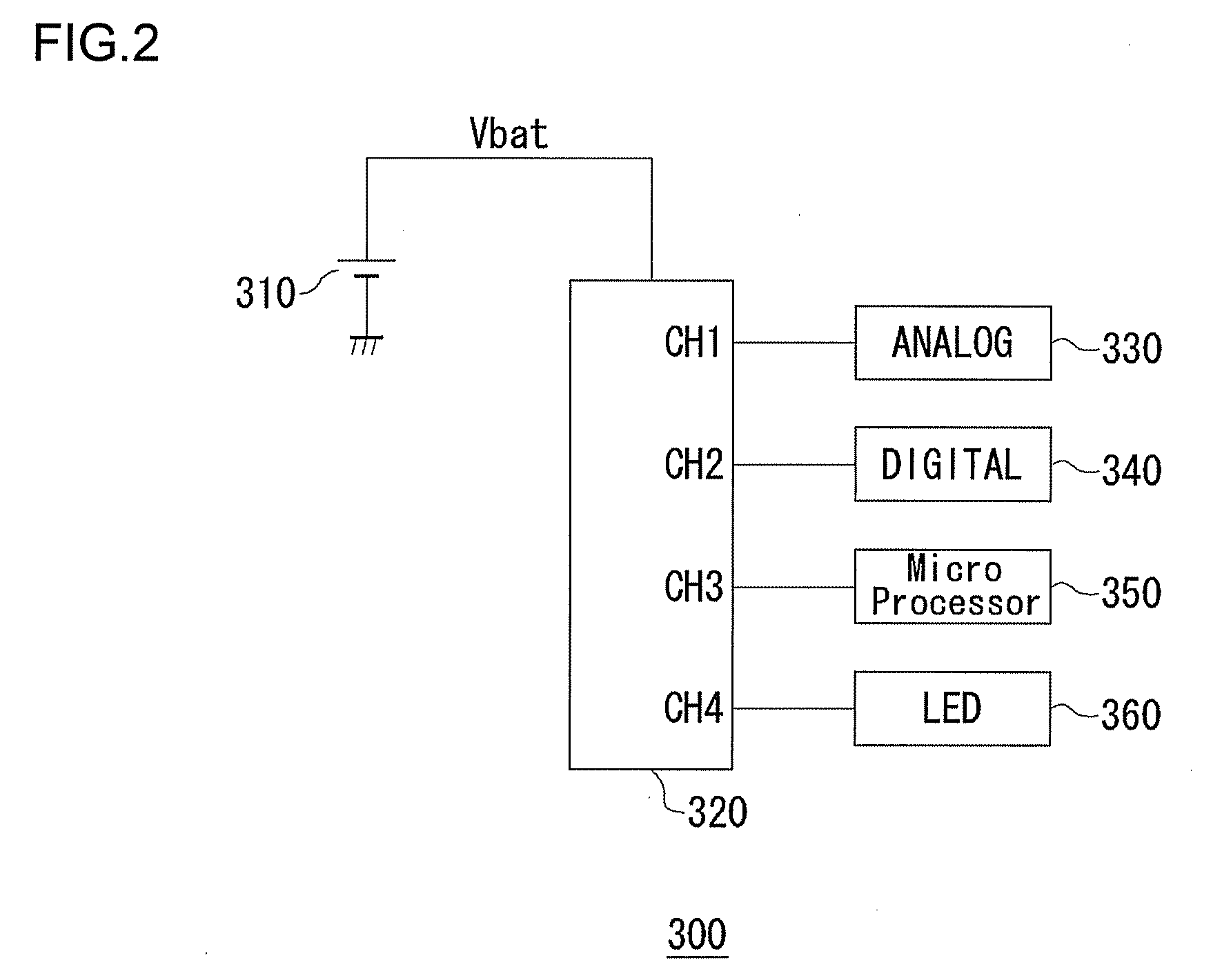
[0042]FIG. 1 is a circuit diagram which shows a configuration of a step-down switching regulator 200 according to an embodiment. FIG. 2 is a block diagram which shows a configuration of an electronic device 300 mounting the step-down switching regulator 200 shown in FIG. 1. The electronic device 300 is a small-sized battery-driven information terminal such as a cellular phone terminal, a CD player, a PDA, or the like, for example. Description will be made below regarding an arrangement in which the electronic device 300 is a cellular phone terminal.

[0043]The electronic device 300 includes a battery 310, a power supply device 320, an analog circuit 330, a digital circuit 340, a microprocessor 350, a...


PUM


Abstract

In a control circuit which turns on / off the switching device elements included in a synchronous rectifier step-down switching regulator, a hysteresis comparator compares the detection voltage that corresponds to the output voltage of the step-down switching regulator with a first threshold voltage and a second threshold voltage. A light-load detection circuit detects whether or not a load is in the light-load state. A driver circuit turns on / off the switching device elements according to the pulse signal output from the hysteresis comparator. Upon the light-load detection circuit detecting the light-load state, the hysteresis comparator shifts the second threshold voltage toward the higher-voltage side by a predetermined voltage difference.

Description

BACKGROUND OF THE INVENTION[0001]1. Field of the Invention[0002]The present invention relates to a step-down switching regulator, and particularly to a control technique for a synchronous rectifier switching regulator.[0003]2. Description of the Related Art[0004]In recent years, microprocessors for providing digital signal processing are mounted in various electronic devices such as cellular phones, PDAs (Personal Digital Assistants), notebook-sized personal computers, etc. The power supply voltage necessary for driving such a microprocessor is being reduced as the fine semiconductor manufacturing process is being improved. For example, a microprocessor is known which operates at a low voltage of 1.5 V or less.[0005]A battery such as a lithium ion battery or the like is mounted on such electronic devices as a power supply. The lithium ion battery outputs voltage of around 3 V to 4V. Such an arrangement, in which the output voltage is directly supplied to the microprocessor, leads to...

Claims


Application Information

Patent Timeline
Patent Type & Authority Applications(United States)
IPC IPC(8): H02M3/137
CPCH02M3/1588Y02B70/16Y02B70/1466H02M2001/0032H02M1/0032Y02B70/10H02M3/155
Inventor FUKUMORI, YOSHITAKA
Owner ROHM CO LTD
Why Eureka
Try Eureka