Oob (out of band) detection circuit and serial ata system

a detection circuit and serial ata system technology, applied in the direction of pulse technique, amplitude demodulation, transmission monitoring, etc., can solve the problems of deterioration in the yield of products and the inability of analog circuits to meet standards, so as to prevent deterioration in the yield of products and accurate signal determination

Inactive Publication Date: 2009-06-11
RENESAS ELECTRONICS CORP
View PDF8 Cites 43 Cited by
  • Summary
  • Abstract
  • Description
  • Claims
  • Application Information

AI Technical Summary

Benefits of technology

[0008]According to the embodiment, even in the case where a characteristic fluctuation occurs in the amplitude determining circuit and the time determining circuit as analog circuits, a threshold and response time in which the fluctuat

Problems solved by technology

There is a case such that characteristics fluctuate due to variations in wafer processes, temperature, and power source voltage, and the analo

Method used


Image

  • Oob (out of band) detection circuit and serial ata system
  • Oob (out of band) detection circuit and serial ata system
  • Oob (out of band) detection circuit and serial ata system

Examples


first embodiment

A. First Embodiment

A-1. Self Adjustment Mechanism of Amplitude Determining Circuit

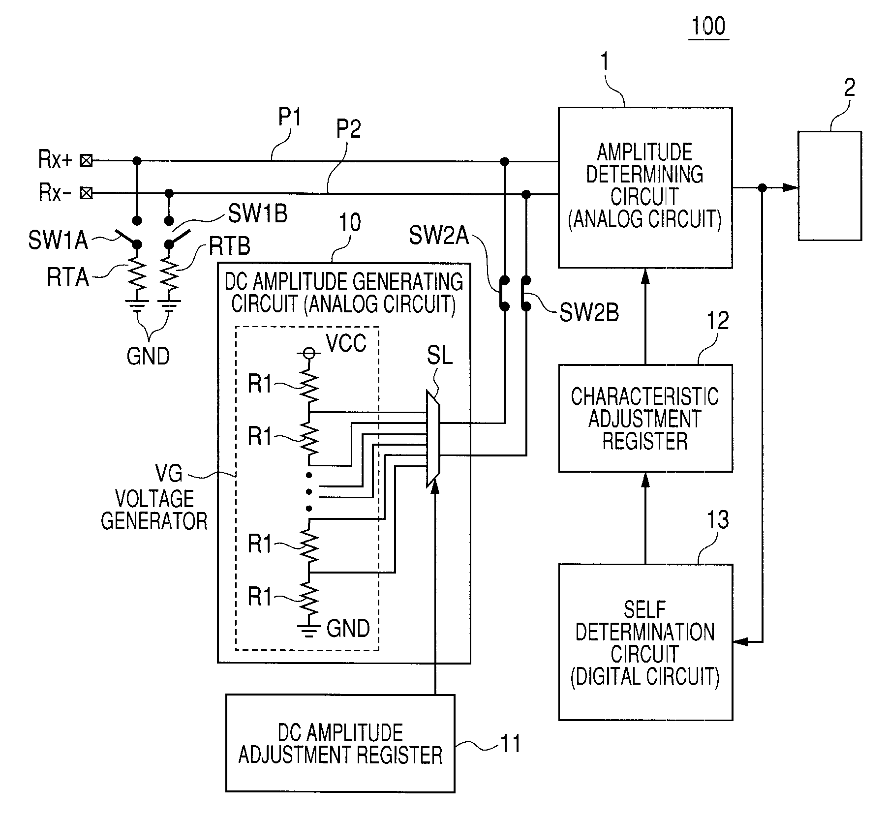
[0037]FIG. 7 is a block diagram showing the configuration of an OOB detection circuit 100 as a first embodiment of the present invention and, particularly showing a self adjustment mechanism of the amplitude determining circuit 1.

[0038]As shown in FIG. 7, the Rx+ port and the Rx− port are coupled to the amplitude determining circuit 1 via signal paths P1 and P2, respectively. Between the signal path P1 and the ground GND, a switch SW1A and a termination resistor RTA are interposed. Between the signal path P2 and the ground GND, a switch SW1B and a termination resistor RTB are interposed.

[0039]The signal paths P1 and P2 are coupled to a DC amplitude generation circuit 10 via switches SW2A and SW2B, respectively.

[0040]The DC amplitude generation circuit 10 has a voltage generator VG for generating various voltages by dividing the voltage between the power source VCC and the ground GND by a plurality of r...

second embodiment

B. Second Embodiment

[0090]In a second embodiment of the present invention, in the SATA system having the OOB detection circuit 100 described in the first embodiment, self adjustment of the amplitude determining circuit 1 and the time determining circuit 2 in the OOB detection circuit 100 is performed. A CPU (Central Processing Unit) recognizes a result of the self adjustment and starts SATA communication.

[0091]FIG. 10 is a block diagram showing the configuration of a microcomputer 200 as an example of an SATA system having the OOB detection circuit 100.

[0092]As shown in FIG. 10, the microcomputer 200 has an MPU (Micro Processing Unit) module MP, a register group RS for transmitting / receiving a predetermined set value to / from a CPU 51 via a bus controller 52 in the MPU module MP, a code memory (as a RAM or ROM) CM storing a program for the bus controller 52, and an SATA module SM.

[0093]The self determination circuit 13 (15) in the OOB detection circuit 100 described with reference to...

third embodiment

C. Third Embodiment

[0105]The microcomputer 200 described in the second embodiment employs the configuration that the CPU recognizes the self adjustment result and starts the SATA communication. In a third embodiment, a configuration that the SATA communication can be started without recognition of the self adjustment result by the CPU will be described.

[0106]FIG. 12 is a block diagram showing the configuration of a microcomputer 300 as a third embodiment. The same reference numerals are designated to the same components as those of the microcomputer 200 shown in FIG. 10 and repetitive description will not be given.

[0107]As shown in FIG. 12, the microcomputer 300 has the SATA communication start bit register RS1 as a register which can be accessed from the CPU 51. The self determination circuit 13 (15) in the OOB detection circuit 100 described with reference to FIGS. 7 and 8 has the self adjustment execution flag register RS2 and the characteristic adjustment register 12 (14) shown ...


PUM


Abstract

The present invention provides an OOB detection circuit capable of making accurate signal determination even in the case where a characteristic fluctuation occurs in an analog circuit, thereby preventing deterioration in the yield of a product. To an amplitude determining circuit, a characteristic adjustment register for changing setting of an amplitude threshold adjustment mechanism for distinguishing a burst and a squelch from each other provided for the amplitude determining circuit is coupled. The characteristic adjustment register is controlled by a self determination circuit. An output of the amplitude determination circuit is supplied to a time determining circuit and also to the self determination circuit. On the basis of the output of the amplitude determining circuit, the self determination circuit controls the characteristic adjustment register.

Description

CROSS-REFERENCE TO RELATED APPLICATIONS[0001]The disclosure of Japanese Patent Application No. 2007-316547 filed on Dec. 7, 2007 including the specification, drawings and abstract is incorporated herein by reference in its entirety.BACKGROUND OF THE INVENTION[0002]The present invention relates to an OOB (Out Of Band) detection circuit in a host and a device, of a system using serial advanced technology attachment (SATA).[0003]In serial advanced technology attachment (hereinbelow, called SATA) as a communication standard between a host of a computer and a device, when a host and a device recover from a power management (called PM mode or PM state) state in which power consumption is returned or make a reset, a specific pattern (OOB pattern) is transmitted from either the host or device to the other side. The receiver has to recognize that the transmitted pattern is an OOB pattern.[0004]An OOB signal is detected by detecting a burst period and a space period (squelch period). The conf...

Claims


Application Information

Patent Timeline
IPC IPC(8): H03L5/00
CPCH03G3/341G06F13/4072G06F13/00G06F13/42
Inventor KUROOKA, KAZUAKISHIMIZU, KENICHI
Owner RENESAS ELECTRONICS CORP
Why Eureka
Try Eureka