
Monopole antenna and wireless network device having the same

a wireless network device and antenna technology, applied in the field of antennas, can solve the problem that the conventional printed antenna cannot meet the requirement of the vertical stand type wireless network device, and achieve the effect of improving antenna performance, improving radiation pattern, and increasing vertical gain

Inactive Publication Date: 2009-06-11
CAMEO COMM
View PDF3 Cites 4 Cited by
  • Summary
  • Abstract
  • Description
  • Claims
  • Application Information

AI Technical Summary

Benefits of technology

[0007]A first objective of the present invention is to provide a uni-planar plated UWB monopole antenna that facilitates fabrication and reduces cost by using a stamping process to integrally form a uni-planar three-dimensional antenna.
[0008]A second object of the present invention is to provide an antenna adapted for use in a wireless network device, which can be quickly assembled to the wireless network device by means of an embedded type design of the antenna, and which has an improved antenna radiation pattern that increases the gain value along a vertical direction and reduces dead spots as well as increases operating bandwidth.
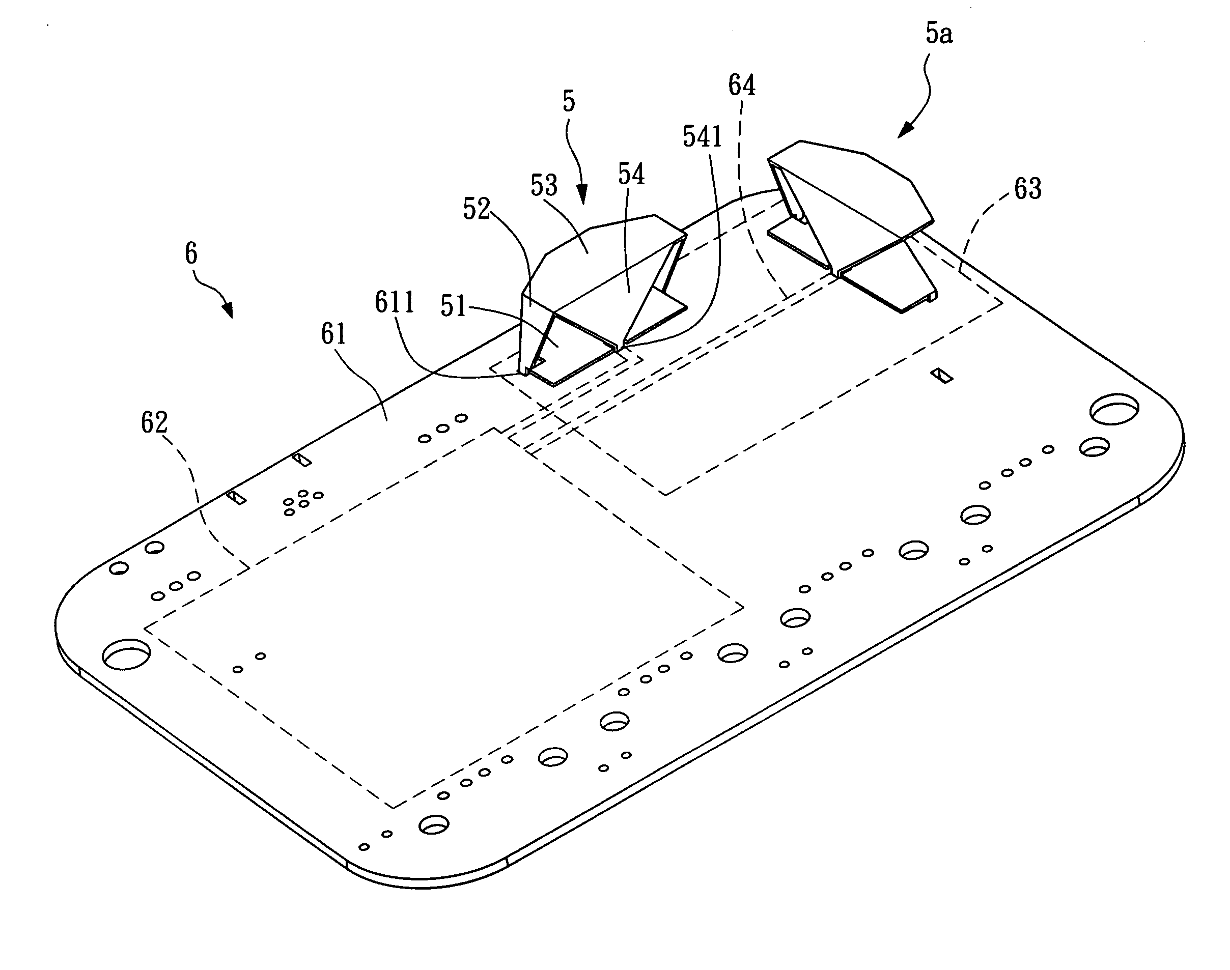
[0009]In order to achieve aforementioned objects, the present invention discloses a monopole antenna adapted for a wireless network device. The antenna comprises a base portion, a ground portion, a radiating portion and a signal portion. The ground portion extends a predetermined height upwardly from the base portion. The radiating portion is connected to an end of the ground portion away from the base portion and is substantially perpendicular to the ground portion. The signal portion is connected to the radiating portion and is substantially and respectively perpendicular to the signal portion and the ground portion. The signal portion has a feed terminal formed on an end thereof away from the radiating portion. A connecting side, where the ground portion and the base portion are connected, has a width that is smaller than a width of another connecting side, where the ground portion and the radiating portion are connected; and a connecting side, where the signal portion and the radiating portion are connected, has a width that is larger than a width of the end of signal portion away from the radiating portion. The antenna is a single component integrally formed by stamping an electrically conductive thin metal plate, which facilitates not only fabrication thereof, but also the assembly of the antenna to a substrate of the wireless network device and increases the gain and bandwidth of the wireless network device along a vertical direction as well.
[0011]When the antenna of the present invention is utilized in a wireless network device, the wireless network device generally includes a substrate, a control circuit and at least one feed line. The substrate may be made of a dielectric material and may have at least one opening defined thereon. The control circuit is formed on the substrate and may provide a wireless network transmitting function. The feed line is coupled to the control circuit. When the antenna assembles onto the wireless network device, a ground terminal of a base portion of the antenna is inserted into the opening, and the base portion is closely contact with a ground of the substrate. A feed terminal of a signal portion of the antenna is coupled to the feed line. The wireless network device can thus be provided with an improved radiation pattern and a higher gain in the vertical direction as well as a significantly increased the antenna performance.

Problems solved by technology

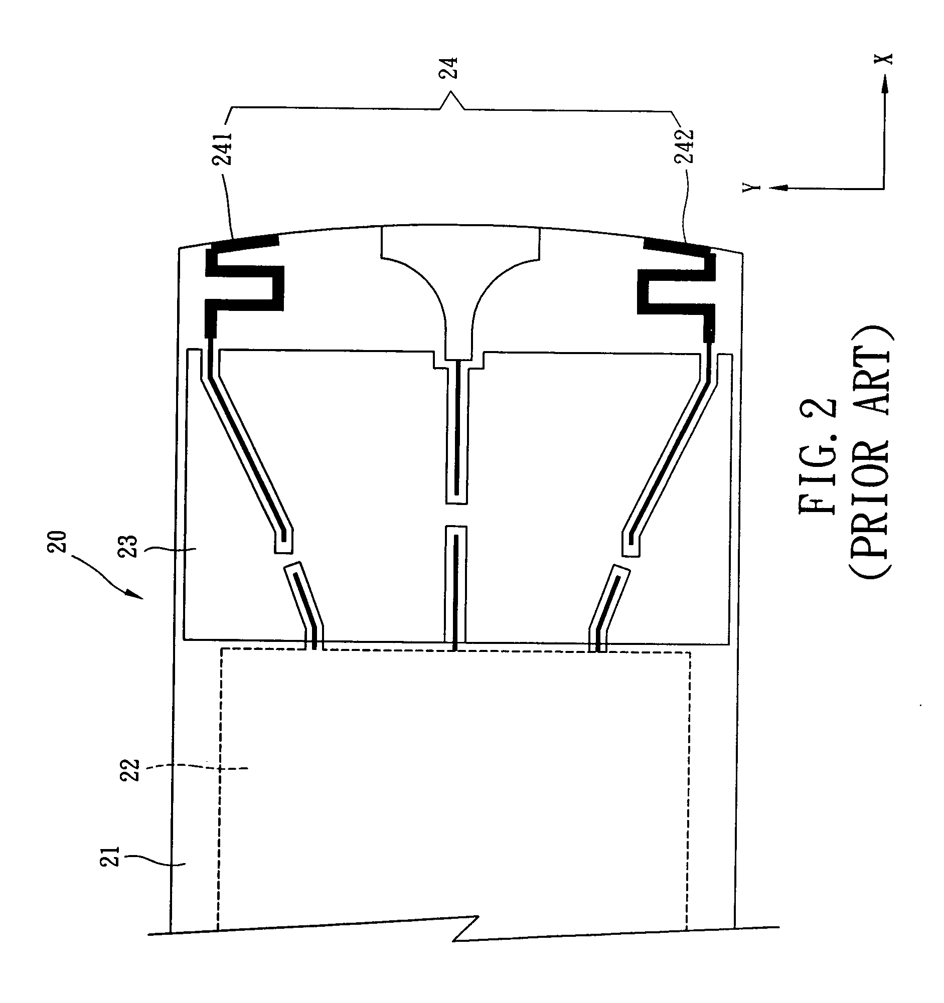
It is obvious that the conventional printed antenna cannot meet the requirement for the vertical stand type wireless network device due to the poor gain along the vertical Z direction.

Method used


Image

  • Monopole antenna and wireless network device having the same
  • Monopole antenna and wireless network device having the same
  • Monopole antenna and wireless network device having the same

Examples


Embodiment Construction

[0024]The main principle of the monopole antenna and the wireless network device having the antenna according to the present invention is that a three-dimensional antenna is integrally formed by using a stamping process and the antenna can be quickly assembled to a substrate of the wireless network device. The height difference between a radiating portion and a base portion of the monopole antenna of the present invention can effectively increase the gain along the vertical direction. In addition, the operating bandwidth is widened by means of a ground portion and a signal portion structure; wherein the ground portion has a unique shape as wide top and narrow bottom. Furthermore, by adjusting a distance formed between a connecting side of the signal portion and the radiating portion, and a connecting side of the ground portion and the radiating portion; thus the operating bandwidth can be adjusted so as to adapt the monopole antenna of the present invention for UWB communication pro...


PUM


Abstract

The present invention discloses a monopole antenna adapted for a wireless network device. The antenna includes a base portion, a ground portion, a radiating portion and a signal portion. The ground portion extends a predetermined height upwardly from the base portion. The radiating portion is connected to an end of the ground portion away from the base portion and is substantially perpendicular to the ground portion. The signal portion is connected to the radiating portion and is substantially and respectively perpendicular to the signal portion and the ground portion. The signal portion has a feed terminal formed on an end thereof away from the radiating portion. A connecting side, where the ground portion and the base portion are connected, has a width that is smaller than a width of another connecting side, where the ground portion and the radiating portion are connected; and a connecting side, where the signal portion and the radiating portion are connected, has a width that is larger than a width of the end of signal portion away from the radiating portion. The antenna is a single component integrally formed by stamping an electrically conductive thin metal plate, which facilitates not only fabrication thereof, but also the assembly of the antenna to a substrate of the wireless network device and increases the gain and bandwidth of the wireless network device along a vertical direction as well.

Description

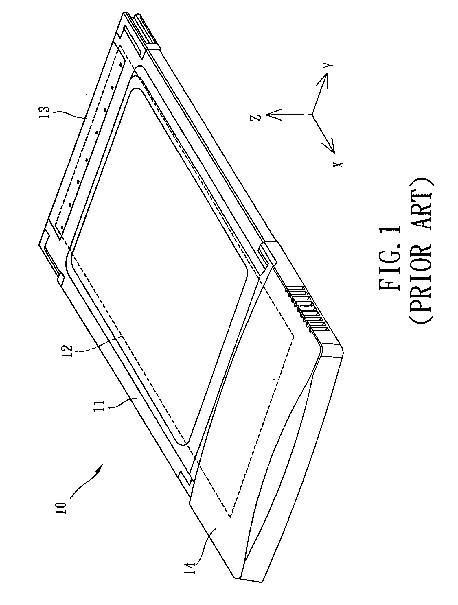
BACKGROUND OF INVENTION[0001]1. Field of the Invention[0002]The present invention relates to antennas, and more particularly, to an integrally formed and uni-planar plated ultra wideband (UWB) monopole antenna adapted for use in wireless network devices, and a wireless network device with the antenna.[0003]2. Description of the Prior Art[0004]FIG. 1 is a perspective view of a conventional wireless network device 10 of a wireless network card, for example. The wireless network device 10 usually includes a main body 11, an internal circuit device 12 located inside the main body 11, a connector portion 13 located at one end of the main body 11 for connecting an external mainframe (not shown), and an antenna signal receiving / transmitting portion 14 located at another end of the main body 11 opposing the connector portion 13. Generally, the antenna signal receiving / transmitting portion 14 is provided with a housing that is made of a non-metal material. When the wireless network device 10...

Claims


Application Information

Patent Timeline
IPC IPC(8): H01Q1/00H01Q1/24
CPCH01Q1/2283
Inventor WU, JUNG TAI
Owner CAMEO COMM
Learn More