Image projection device

a projection device and image technology, applied in the field of image projection devices, can solve the problems of difficult mounting of large-sized displays, increased power consumption, and eye stimulation of projection light, and achieve the effects of reducing the number of parts, reducing the cost, and reducing the size of the apparatus

Inactive Publication Date: 2009-06-11
PANASONIC CORP
View PDF5 Cites 102 Cited by
  • Summary
  • Abstract
  • Description
  • Claims
  • Application Information

AI Technical Summary

Benefits of technology

[0038]According to the present invention, a mirror section for image displaying purposes serves also as a mechanism for detecting an image displayable region. As a result, the number of parts is reduced so that a cost reduction is realized, and downsizing of the apparatus can also be realized. Moreover, the calculation section distinguishes between an image displayable region which is determined as not containing any humans and any other region determined as containing a human(s). Safety can be ensured by not displaying an image in any region determined as containing a human(s). In addition, it is possible to display an image with strong light in the image displayable region, which is determined as not containing any humans, whereby a bright image displaying can be realized.
[0039]In one embodiment, an image displayable region is detected by using laser light for displaying an image. By merely providing in the apparatus a detection section for detecting reflected light intensity and a calculation section in addition to the constituent elements for image displaying purposes, it becomes possible to perform detection of an image displayable region. Thus, a further cost reduction and downsizing of the apparatus can be realized. According to the present invention, since it is not necessary to separately provide a sensor(s) for detection and a camera(s) for image monitoring in the apparatus as a mechanism for detecting objects and people, an image projection apparatus can be realized which is small-sized and inexpensive and yet enables bright image displaying in a safe manner.
[0040]In one embodiment, the operation of detecting humans is continued in both the image displayable region and any other region. As a result, when a human has intruded the image displayable region, image displaying in the intruded region can be immediately suspended. On the other hand, when humans are no longer detected from any region other than the image displayable region, image displaying in that region can be resumed.
[0041]In one embodiment, the laser light for detection purposes is projected in a dot pattern. As a result, the operation of detecting humans can be performed while ensuring safety by reducing the amount of light that might enter human eyes.
[0042]In one embodiment, the process of determining an image displayable region is performed for each scanning line, and a result of this process is reflected on a modulation of the laser light corresponding to a subsequent scanning line. Thus, by performing the process for each scanning line, image displaying and non-displaying can be switched with minimum processing time. Moreover, by allowing the processing result to be reflected on the subsequent scanning line, the amount of light that might enter human eyes can be further reduced.
[0043]In one embodiment, the calculation section determines the image displayable region based further on an intensity of light which is detected by the detection section in a blanking period during which the light source is not lit. By detecting light other than reflected light of the laser light, it becomes possible to precisely determine the image displayable region under various conditions, e.g., brightness or darkness of the place of use and the state of an object in the projection region.

Problems solved by technology

When a human comes into a projection light path between a projector for projecting an image onto a screen and the screen and turns his or her face toward the projecting side, there is a danger in that the projection light may stimulate his or her eyes.
Such a scanning-based laser projector displays an image by modulating the intensity of laser light, and thus is even more power-thrifty than any usual projector that uses two-dimensional image displaying devices, e.g., a liquid crystal panel or a DMD (Digital Micromirror Device).
Thus, large-scale displaying can be enjoyed even with a mobile phone or the like, in which a large-sized display would be difficult to be mounted.

Method used


Image

  • Image projection device
  • Image projection device
  • Image projection device

Examples


embodiment 1

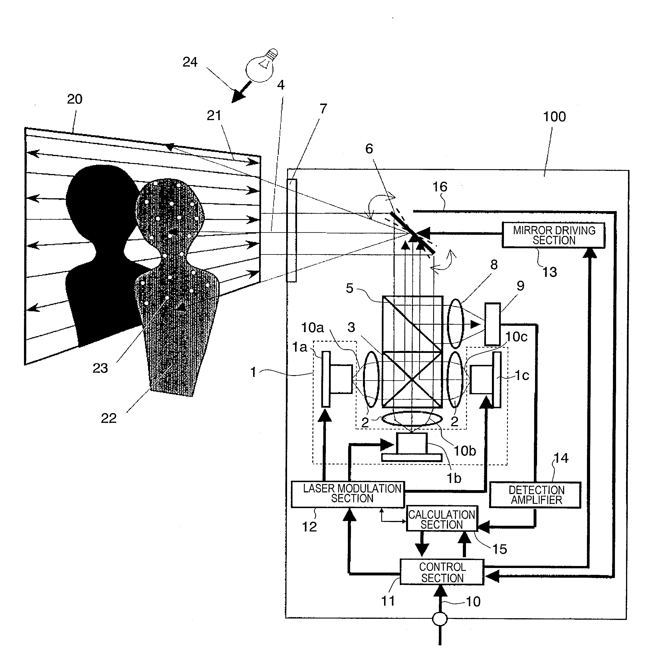
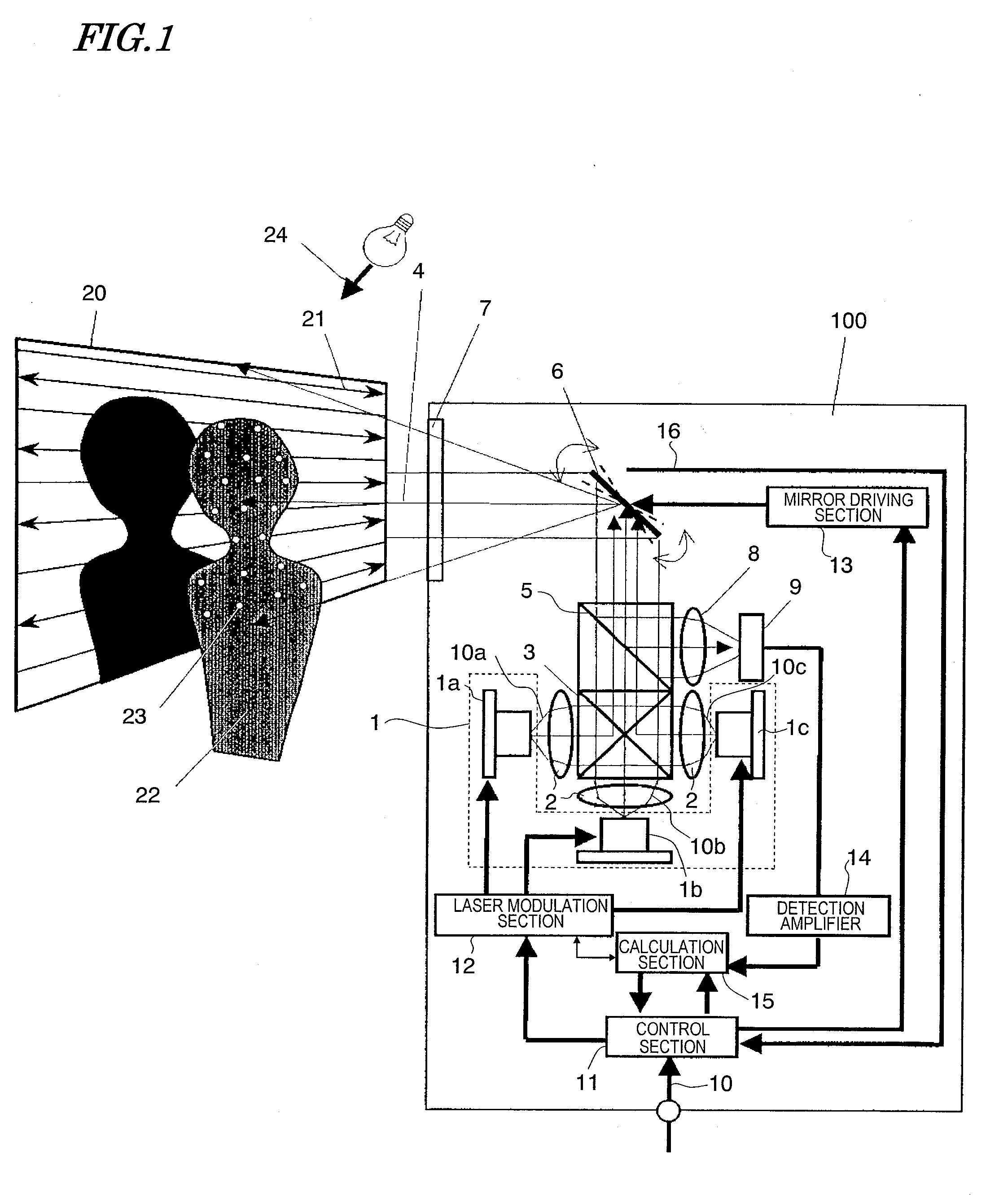
[0088]With reference to FIG. 1 to FIG. 6, a first embodiment of an image projection apparatus according to the present invention will be described. First, FIG. 1 will be referred to. FIG. 1 is a diagram showing an image projection apparatus 100 according to the present embodiment. The video projection apparatus 100 displays an image on a screen or the like with at least a portion of projected laser light. In the video projection apparatus 100, laser light and a mirror section for image displaying purposes are also utilized for an operation of detecting an image displayable region. As a result, cost reduction is realized based on a reduced number of parts, and downsizing of the video projection apparatus 100 can also be realized.

[0089]The image projection apparatus 100 includes a light source 1 for outputting laser light 10a to 10c, collimating lenses 2, a dichroic prism 3, a half mirror 5, and a mirror section 6 for allowing the laser light 10a to 10c to be reflected and projected. ...

embodiment 2

[0181]Next, with reference to FIG. 7 to FIG. 12, a second embodiment of an image projection apparatus according to the present invention will be described. FIG. 7 is a diagram showing an image projection apparatus 200 according to the present embodiment.

[0182]The image projection apparatus 200 measures the distance between a screen 20 and the image projection apparatus 200, and detects an obstacle (e.g., a human) from the measurement value. For example, the distance and tilt between the screen 20 and the image projection apparatus 200 are previously measured, and the measurement results are stored. Concurrently with the image displaying, distance measurement is continued, and by making a comparison between the stored distance and the newly measured distance, intrusion of an obstacle can be detected. Note that the distance between a projection target such as the screen 20 and the image projection apparatus 200 refers to the distance between the projection target and an arbitrary posi...

embodiment 3

[0210]FIG. 13 is a diagram showing an image projection apparatus 300 according to Embodiment 3 of the present invention. FIG. 14 is a perspective view describing subregions (plane determination regions); FIG. 15A is a perspective view describing an exemplary plane determination calculation for subregions; and FIG. 15B is a perspective view describing another exemplary plane determination calculation for subregions.

[0211]In the image projection apparatus 300, before performing image displaying, a distance and a tilt between the image projection apparatus 300 and an image-projected region are automatically calculated, and a substantially planar region and its planar position are extracted. At the time of image displaying, an obstacle is detected by determining whether or not the measured distance coincides with the distance to the extracted plane. Moreover, the system controller 11 divides a plane corresponding to the projection target, as obtained based on distance, into a plurality ...


PUM


Abstract

An image projection apparatus according to the present invention includes a light source for outputting laser light and a mirror section for reflecting and projecting the laser light having been output from the light source, and displays an image with at least a portion of the projected laser light. The image projection apparatus includes a detection section for detecting at least a portion of the laser light returning from a projection direction of the laser light, and a calculation section for determining an image displayable region based on the detected light. The mirror section reflects at least a portion of the laser light returning from the projection direction of the laser light so as to be led into the detection section.

Description

TECHNICAL FIELD[0001]The present invention relates to an image projection apparatus for projecting laser light to display an image, and in particular to a technique of improving the safety of an image projection apparatus.BACKGROUND ART[0002]When a human comes into a projection light path between a projector for projecting an image onto a screen and the screen and turns his or her face toward the projecting side, there is a danger in that the projection light may stimulate his or her eyes. Therefore, a method has been proposed in which a detection section for detecting the presence or absence of an object in the projection light path and a control section for controlling radiation power are provided in an image projection apparatus, and when an object is detected in the projection light path, the radiation power is reduced to prevent danger.[0003]For example, Patent Document 1 discloses an image projection apparatus which monitors a projection region with an electromagnetic radiatio...

Claims


Application Information

Patent Timeline
Patent Type & Authority Applications(United States)
IPC IPC(8): G03B21/28
CPCG03B21/14H04N9/3161H04N9/3129G03B17/54G03B21/2033
Inventor KUROZUKA, AKIRATOMITA, HIRONORIKAJINO, OSAMUOBI, HIROSHIMOHRI, MASANARI
Owner PANASONIC CORP
Why Eureka
Try Eureka