
Receiver and communication system having the same

a communication system and receiver technology, applied in the field of communication systems, can solve the problems of increasing the bit error rate (ber), degrading the performance of the cdr, and using clock signals in the communication system, and achieve the effect of reducing the jitter nois

Active Publication Date: 2009-06-11
SAMSUNG ELECTRONICS CO LTD
View PDF10 Cites 14 Cited by
  • Summary
  • Abstract
  • Description
  • Claims
  • Application Information

AI Technical Summary

Benefits of technology

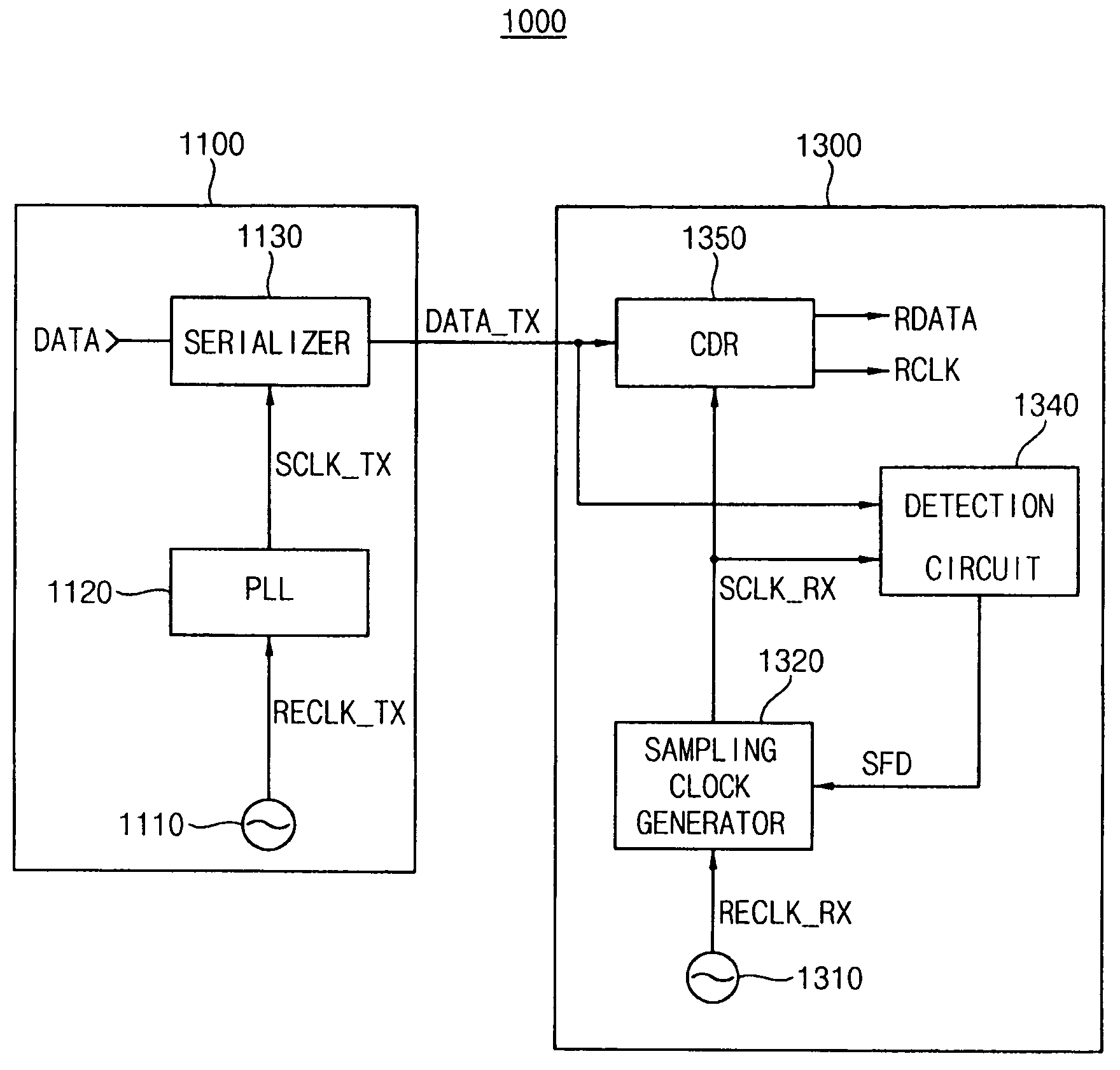
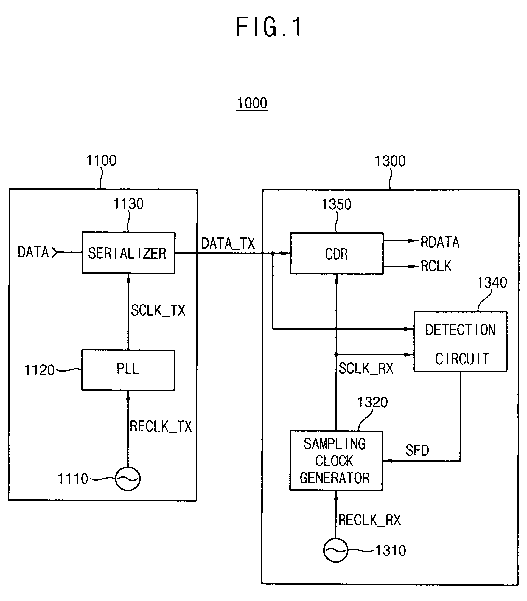
[0010]Example embodiments may provide a receiver for generating a clock signal of which a frequency is substantially identical to a frequency of a clock signal of a transmitter by detecting a frequency difference between the clock signals of the receiver and the transmitter.
[0024]Consequently, according to the example embodiment, a communication system may include the feedback loop implemented with the detection circuit and the sampling clock generator in the receiver so that the receiver adaptively synchronizes the reception sampling clock signal with the transmission sampling clock signal. Accordingly, the communication system may reduce a jitter noise caused by a frequency difference between the reception sampling clock signal and the transmission sampling clock signal.

Problems solved by technology

However, the phases of the clock signals used in the receiver and the transmitter in the communication system using the mesochronous transmission method are different from each other.
The sinusoidal jitter caused by frequency difference between the clock signals of the receiver and the transmitter degrades performance of the CDR and increases a bit error rate (BER).

Method used


Image

  • Receiver and communication system having the same
  • Receiver and communication system having the same
  • Receiver and communication system having the same

Examples


Embodiment Construction

[0035]Example embodiments will now be described more fully with reference to the accompanying drawings.

[0036]Accordingly, while example embodiments are capable of various modifications and alternative forms, embodiments thereof are shown by way of example in the drawings and will herein be described in detail. It should be understood, however, that there is no intent to limit example embodiments to the particular forms disclosed, but on the contrary, example embodiments are to cover all modifications, equivalents, and alternatives falling within the scope of example embodiments. Like numbers refer to like elements throughout the description of the figures.

[0037]It will be understood that, although the terms first, second, etc. may be used herein to describe various elements, these elements should not be limited by these terms. These terms are only used to distinguish one element from another. For example, a first element could be termed a second element, and, similarly, a second ele...


PUM


Abstract

A receiver may include a clock and data recovery circuit, a detection circuit and a sampling clock generator. The clock and data recovery circuit may receive first data and sample the first data to generate recovered data in response to a reception sampling clock signal. The detection circuit may detect a frequency difference between a transmission sampling clock signal and the reception sampling clock signal by comparing the first data and the reception sampling clock signal to generate a frequency difference detection signal. The sampling clock generator may generate the reception sampling clock signal based on the frequency difference detection signal and a first reference clock signal. Therefore, a communication system including the receiver may effectively reduce a jitter noise.

Description

PRIORITY STATEMENT[0001]This application claims priority under 35 U.S.C. §119 to Korean Patent Application No. 2007-0126789, filed on Dec. 7, 2007 in the Korean Intellectual Property Office (KIPO), the entire contents of which are incorporated herein by reference.BACKGROUND[0002]1. Technical Field[0003]Example embodiments relate to a communication system, for example, to a receiver and a communication system having the same.[0004]2. Description of the Related Art[0005]Communication systems typically include a transmitter and a receiver. Data transmission methods of the communication systems are divided into a synchronous transmission method, a mesochronous transmission method, and a plesiochronous transmission method according to clock signals used for sampling data in the receiver.[0006]In the communication system using the synchronous transmission method, a frequency and a phase of a clock signal used in a receiver are substantially the same as a frequency and a phase of a clock s...

Claims


Application Information

Patent Timeline
IPC IPC(8): H04L7/00
CPCH03L7/00H04L7/005H04L7/02H04L7/0012H04B1/06
Inventor SHIN, JONG-SHIN
Owner SAMSUNG ELECTRONICS CO LTD
Learn More